Rudder Pedals
Avionics Research
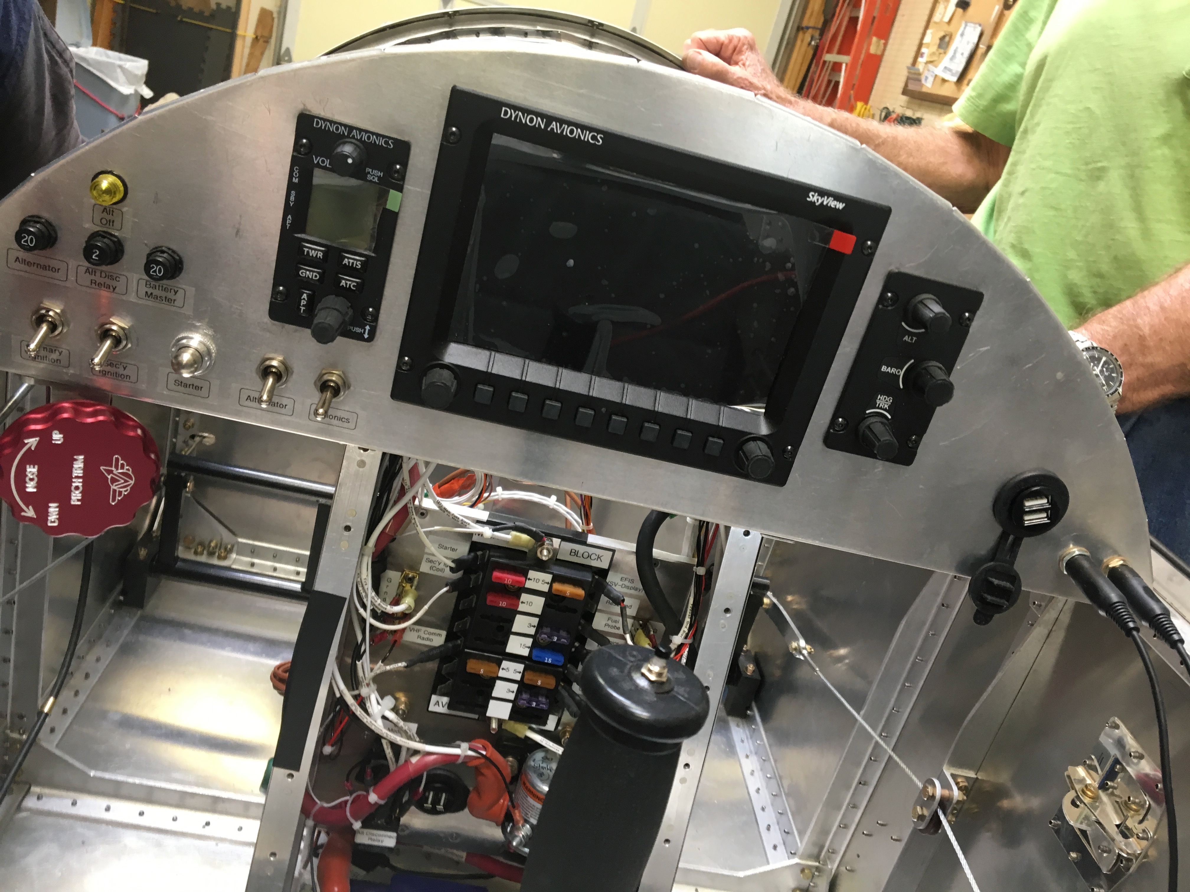
Denny was kind enough to let me visit his build again and ask questions about avionics. After doing research at Oshkosh and on the web, I’ve decided to go with Dynon Avionics in a very similar configuration to Denny. But there are hundreds of questions I had about the electrical/avionics system and Denny was kind enough to answer them for me.
Rudder Pedals
The pedals are mounted using a phenolic blocks. One on each side and one in the middle. These had to be trimmed and sanded to fit. Even after putting together whole rudder system, the pedals where too tight and I had to take it apart and sand down the holes more. That made all the difference.
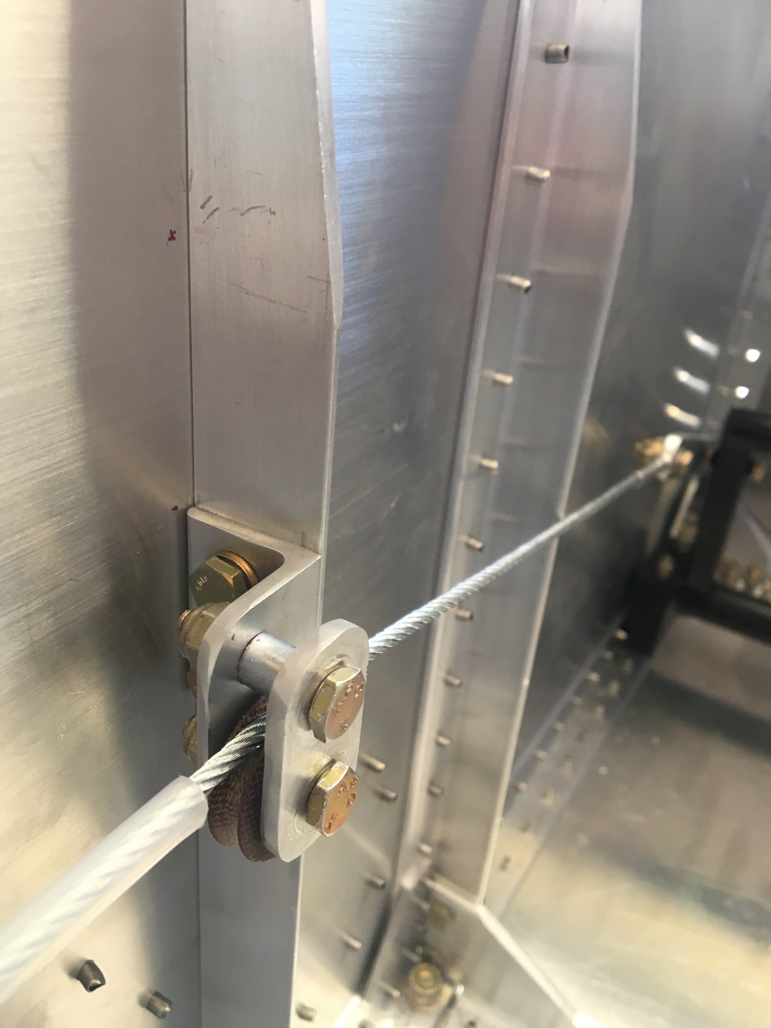
Cable Adjusters
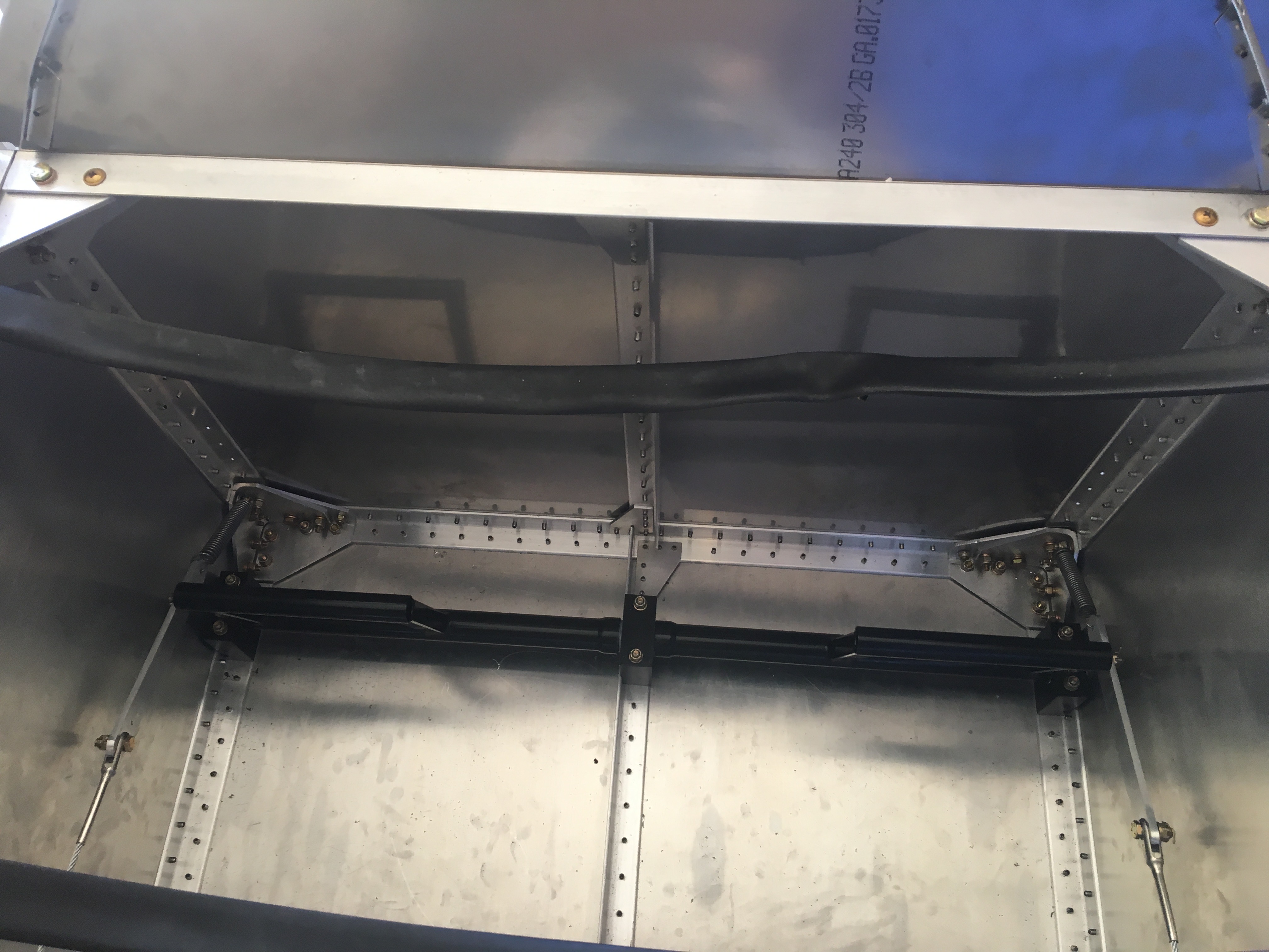
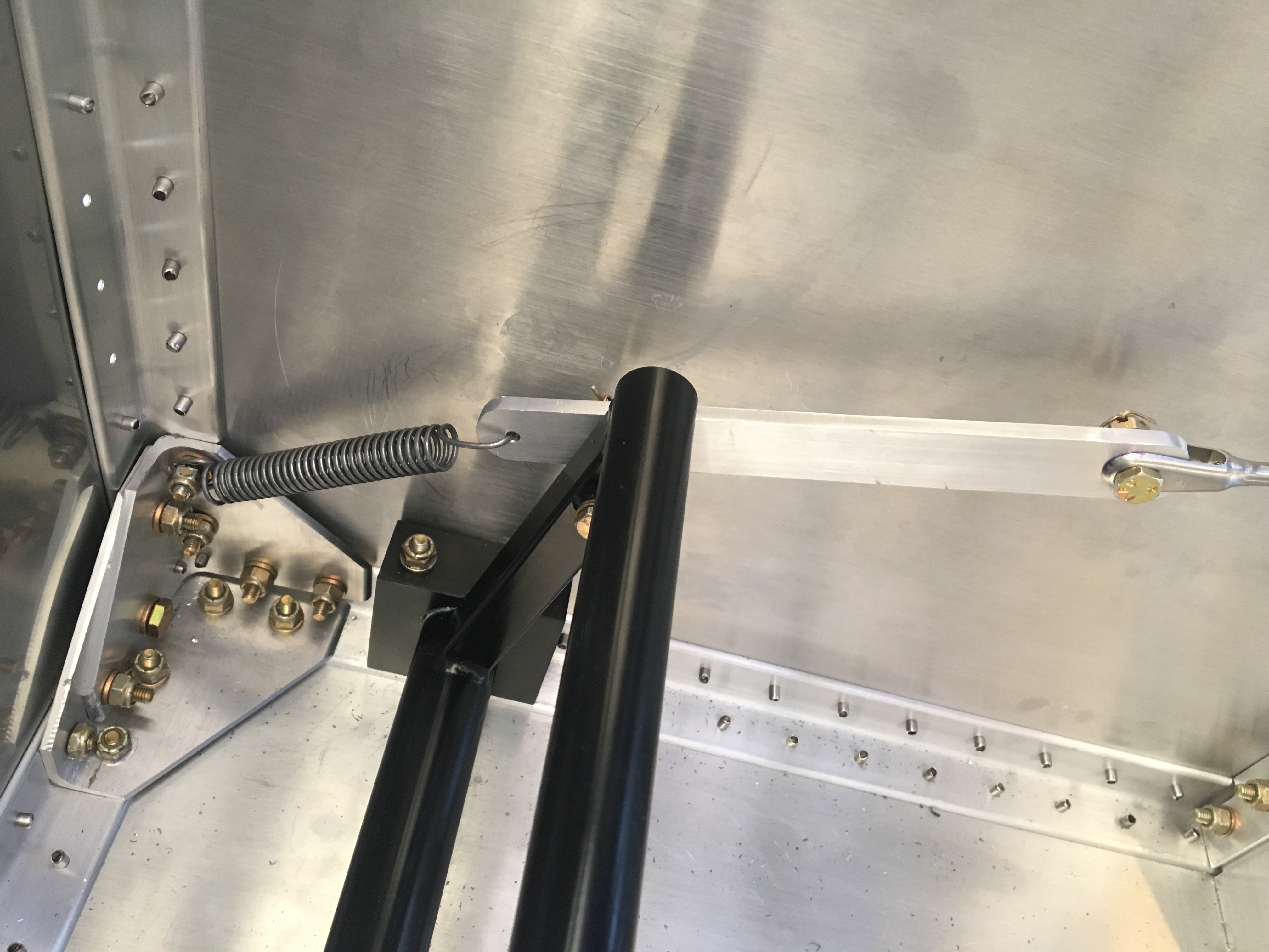
The aluminum bar is called the adjuster. The location where the cable attaches does all the magic. The plans give detailed instructions on how to calculate where to drill the cable hole, but they didn’t work for me. What I was left with was pedals that restricted each other’s movement and the rudder couldn’t even get close to its stops. So I had to fabricate these parts from scratch and use my own technique to calculate the cable attach points. Basically I started by moving the rudder to its full right stop. Then positioned the left pedal as far aft as it would go and marked the attach point. This would allow full right rudder and the left cable would not restrict it. Then I did the opposite for the right pedal. This worked great.
The springs pull the rudder to neutral when foot pressure is released. At first I couldn’t get the springs tight enough to move the rudder. This is when I realized I had to loosen the pedals by sanding the phenolic blocks. With looser pedals, the springs could do their job. The kit came with two long springs that had to be cut and bent to length, but I only used about 2/3 of one of the springs.
Pulleys
There are six pulleys all together that keep the cable where it belongs and allow it to move easily. Four of the pulleys I had build a while back when I first started on the fuselage. The plans said it’d be easier to mount the rear pulleys at that point. Not really. And fortunately I hadn’t riveted them back then. They had to be removed and I had to crawl inside the fuselage many times and in all locations. There was no effort saved but I was pleased to have four fewer parts to fabricate this week.
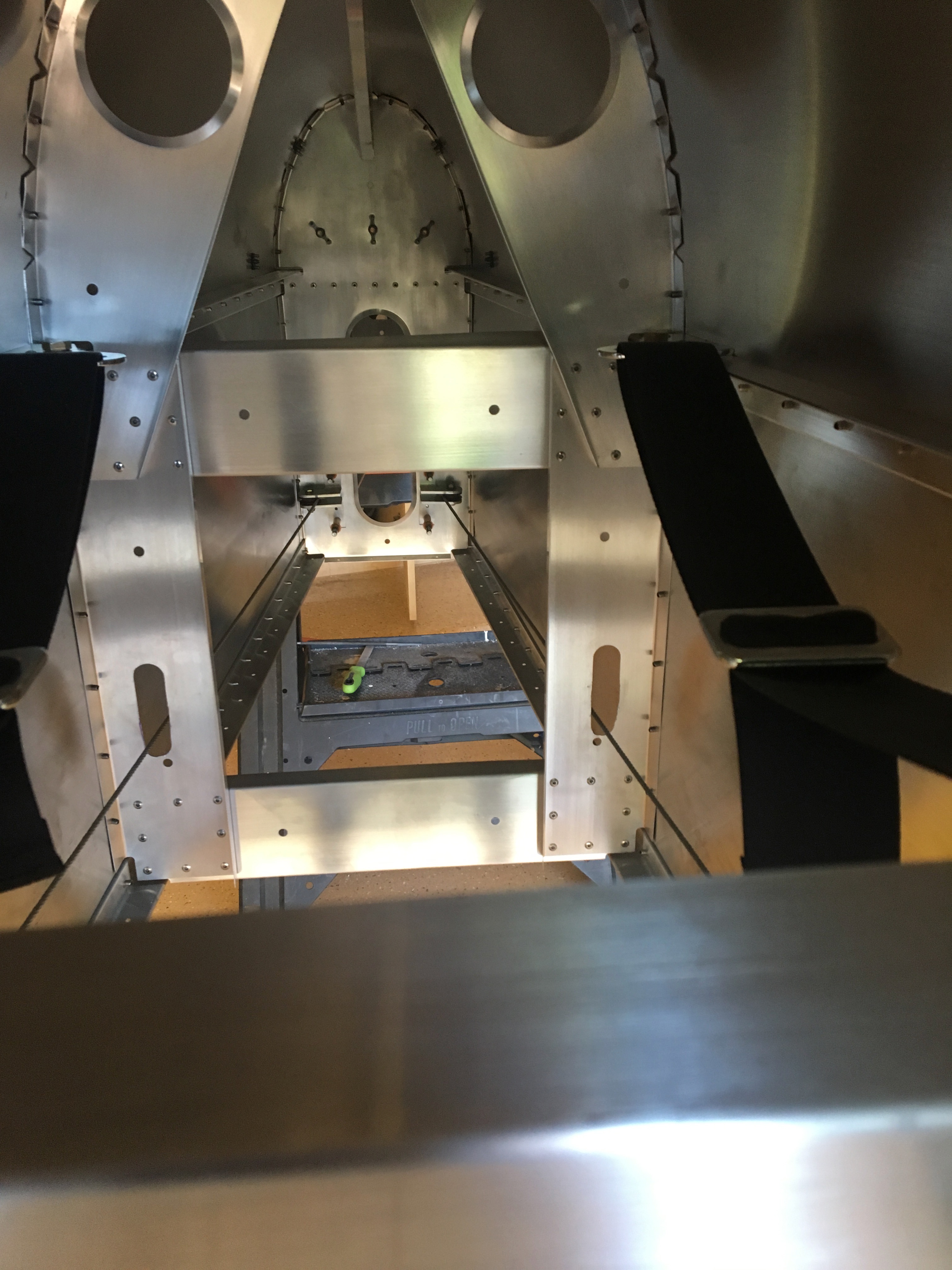
Cable Run
The bulkheads have cutouts that would be ideal for rudder cable to run through. Unfortunately, they’re in the wrong place. I couldn’t believe it at first, but when I visited Denny, he complained about the same problem. So extra holes had to be cut and existing holes elongated in the four center bulkheads.
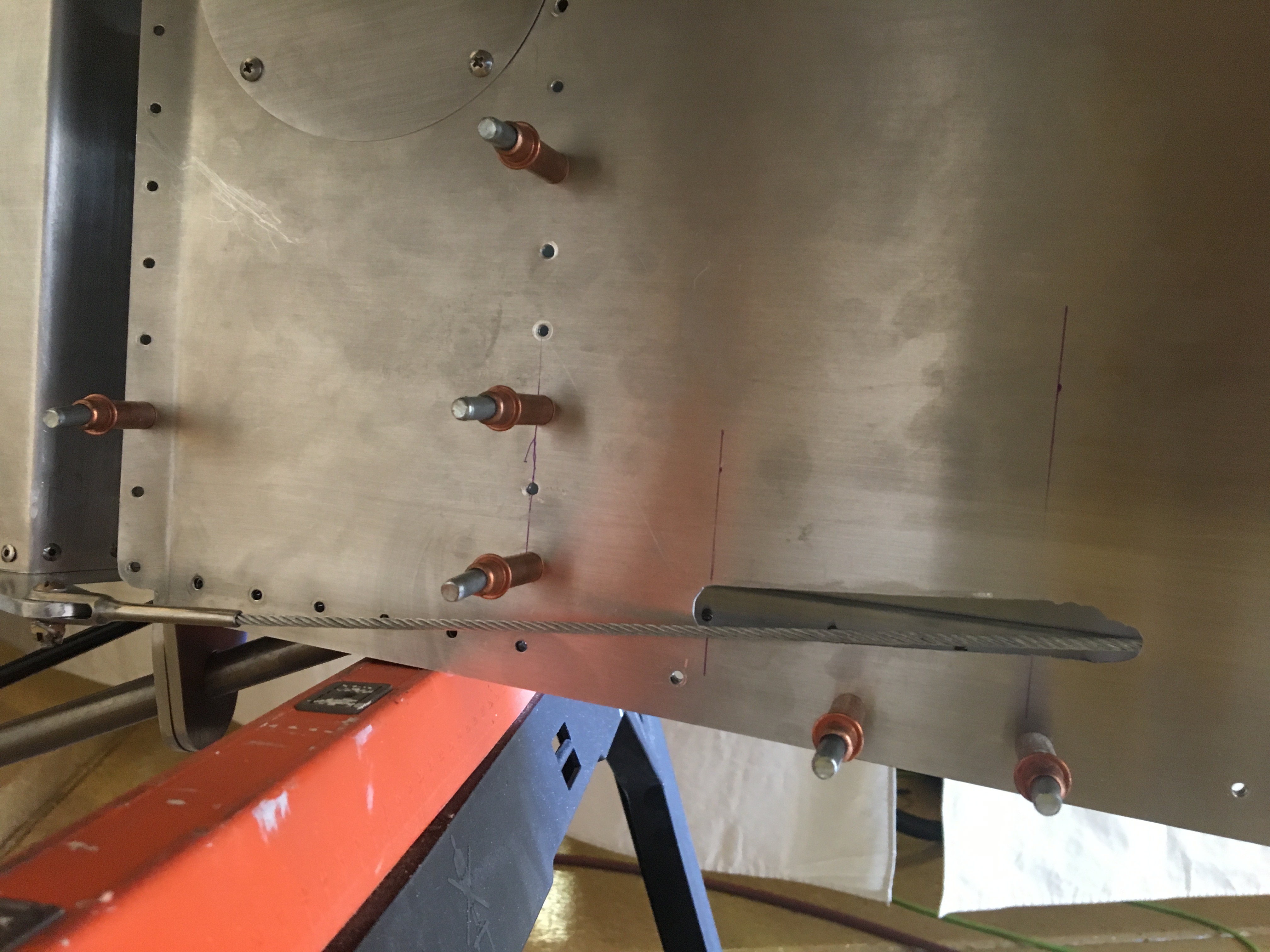
Tail Cable Exit Holes
It was a puzzle to me how I’d calculate exactly where the cables would pass through the skin in the rear of the fuselage. Fortunately, the plans give precise locations and sizes for these holes. Unfortunately, they’re not perfect. The cables rub up against the edges of the skin.
I spent a good deal of time widening and elongating these holes to eliminate the chafing. The left side was not terribly off. The right side is still in progress. I’ve already filed away an extra inch of skin and the cable is still chafing. I’ll continue filing on monday and tidy up the edges so it looks intentional.