eBike: BMS
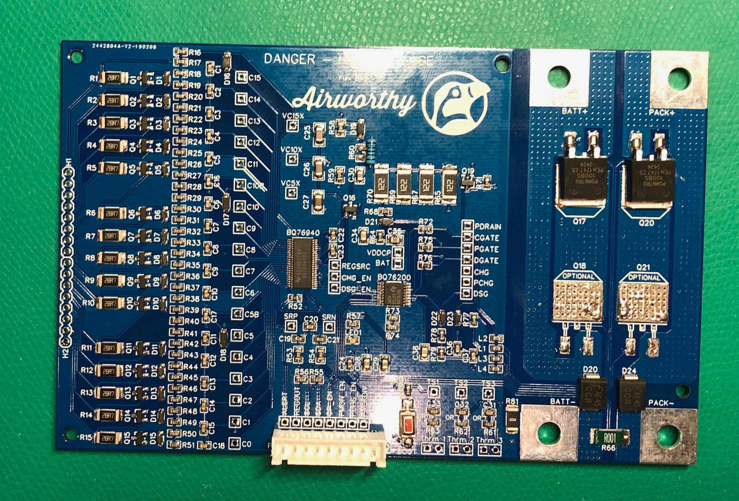
As mentioned in the previous blog about BMS, I designed a PCB (printed circuit board) to accommodate the BQ76940 (monitoring chip) by TI (Texas Instruments). This board has served me well so far in multiple applications. Below is a picture of the BMS board fully populated.
Components & Features
MOSFETS
Metal Oxide Field Effect Transistors (MOSFETs or FETs) are the gates for incoming (charge) current and outgoing (discharge) current. The picture above only has two, but 4 can be installed to share the load. In normal operation, all FETs are “ON” allowing current to flow in both directions. But when something goes wrong, say the batteries voltage is too low, the discharge FETs can be turned off protecting the cells from being drained too much. Or if the charge voltage is too high the charge FETs can be turned off to, again, protect the cells.
FET Driver
The FETs are N-Channel MOSFETs. Without going into too much detail, just know that N-Channel FETs need a relatively high voltage to be turned on. And if you don’t turn them on fast or hard enough, they can get really hot. So that’s what the driver takes care of. When you tell the driver to turn on a FET, through use of a charge pump, it sends a nice high voltage with plenty of current to turn that FET on hard.
Voltage Senors
The monitoring chip (BQ76940) does most of the hard work here, but there are plenty of components involved in getting the chip connected to both ends of each cell. This is all the small stuff on the left side of the board. The voltage of each cell is measured up to 4 times a second.
Balance Circuits
For each cell there are several components, most notably a transistor and power resistor all the way on the left, that allow the board to slowly drain current from each cell individually. Typically while charging, if one or more cells has a higher voltage than the others, it can be “balanced” back down to a voltage that matches its peers.
Current Measuring
In the lower right, between the BATT- and PACK- terminals, there’s a 0.001 ohm resistor through which all pack current flows. Using Ohm’s Law (V=IR), the voltage on each side of the resistor can be measured to determine how much current is flowing in or out of the battery.
Pre-Charge Circuit
The four power resistors lined up near the top center are power resistors used to charge the cells at a very slow rate. This is handy when the cells have been over-depleted and full charge current would damage them.
Controller Interface Pins
Although this BMS circuit can do a ton of stuff, it’s without brains. To complete the task, some software running on a microcontroller is needed. The connector on the bottom center is where the controller is connected.
Microcontroller
Arduino Nano
In the picture below, the BMS is all connected in a test environment.
- The cells are all connected through the balance wires.
- The positive and negative terminals are connected to BATT+ and BATT- respectively.
- The “load” is connected to PACK+ and PACK-.
- The controller is connected to the interface pins
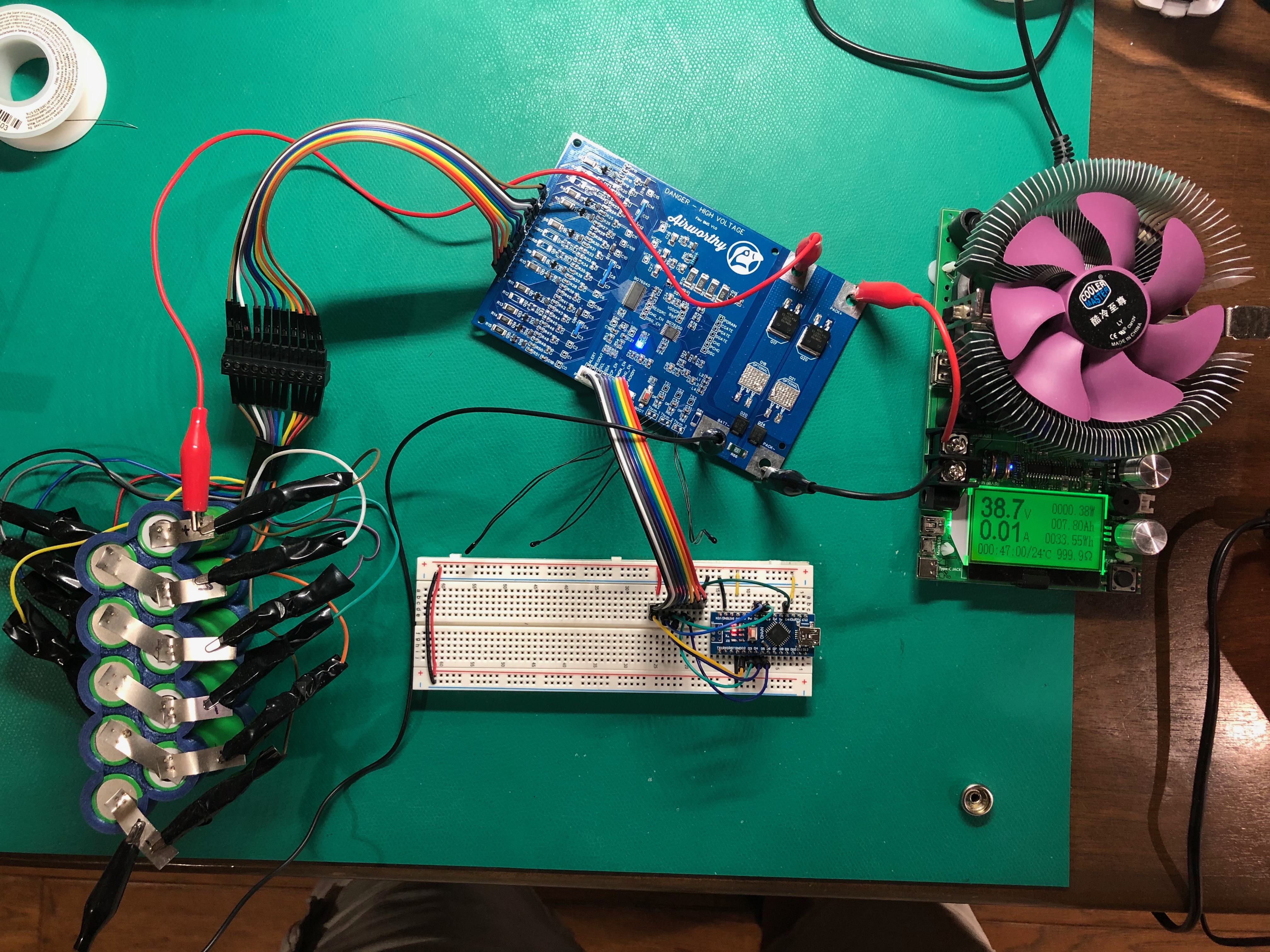
Here, I was using an Arduino Nano as the microcontroller. It worked. But programming in C/C++ is, well, wordy and slow. The Nano also lacks in the memory department. I was reaching the limits of how much code I could put on the poor chip and I had only just gotten started.
Adafruit Feature / CircuitPython
Adafruit sells a wonderful line of boards called Feathers. Not only are they much beefier than the Arduino Nano, but they come equipped with CircuitPython which means you can program them in Python! Now, Python is not my favorite language, but compared to coding in C, it tastes like ambrosia, nectar of the gods.
I started with the Feather M0, and progress was quick. But Python consumes a LOT more memory than C, and runs at a fraction of the speed. It wasn’t long before I hit a wall and had to upgrade to the Feather M4. I made much more progress with that board, but there was another problem.
Adafruit, bless their hearts, caters to beginners. As a consequence, writing code in CircuitPython was like riding a bike with training wheels. The friendliness of the environment wore off fast and I was hindered every step I took.
PyBoard / MicroPython
MicroPython is the ancestor of CircuitPython and it keeps things real. PyBoards, which are similar to the Feathers, are designed specifically to run MicroPython and include plenty of peripheral hardware (like an accelerometer) to keep things interesting.
On the PyBoard, I was was able to plow through and accomplish all my goals. The finished BMS not only included the main battery protection circuit, but also a little OLED screen to monitor the pack and a rotary encoder to interact with it.
Electric Skateboard 2.0
The first use of this freshly squeezed BMS was the skateboard. Sadly, the previous not-so-smart BMS that was installed in the skateboard had failed and allowed the cells to fully drain. They were no good any longer. So I built a new pack of cells, installed the BMS, and 3D-printed a new cover. See below.
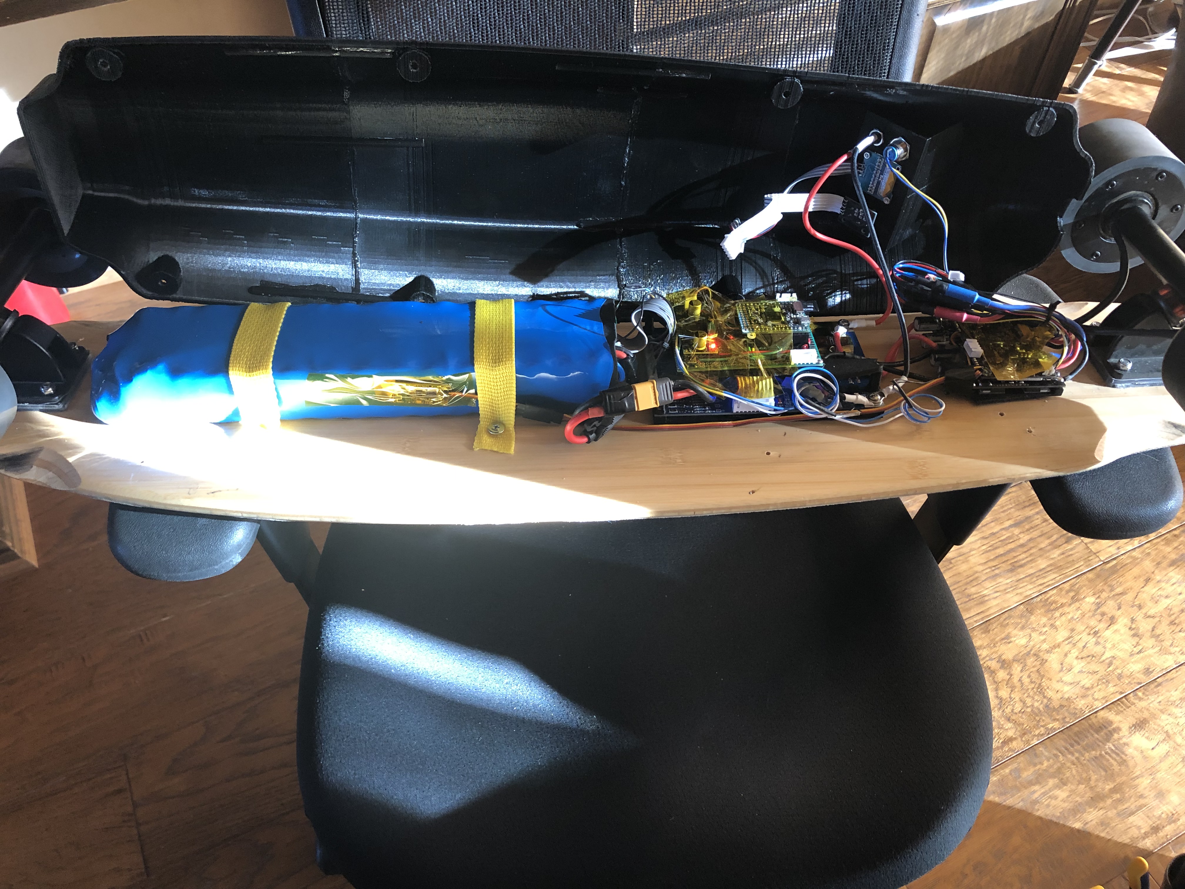
The new cells are on the left. The BMS is in the middle with the PyBoard stacked on top using a 3D printed mount I designed. And on the right is the motor speed controller. Attached to the cover is the OLED screen and rotary encoder with dangling wires that get connected to the PyBoard’s circuitry.
You may notice that there is also a buck converter stacked on top of the BMS. The BMS board does provide about 20 mA of power, but it’s not enough for the PyBoard, OLED screen, and rotary encoder. The buck converter takes the 36V juice directly from the batteries and feeds the other devices at 3.3V.
Works Too Well
The BMS in the skateboard worked perfectly! It did everything I programmed it to do. But the real world is not perfect.
You see. When a speed controller says it uses 30A max, it really uses up to 31 or 32 amps some times. My BMS saw that said “Shut The Front Door!” And when a charger says it charges at 42V, it really charges at 42.3 or even 43V. Again, my BMS saw this and said “Foul! Red Card!” The problems kept coming and my perfect little BMS became a paranoid schizophrenic. I put it on Lithium (see what I did there?) and updated its code to “model the real world”.
Not long after, I was riding skateboard 2.0 around the neighborhood and life was good. With that accomplishment under my belt I called my brother Justin and told him I was ready to build some battery packs for his derelict moped. I already told that story.
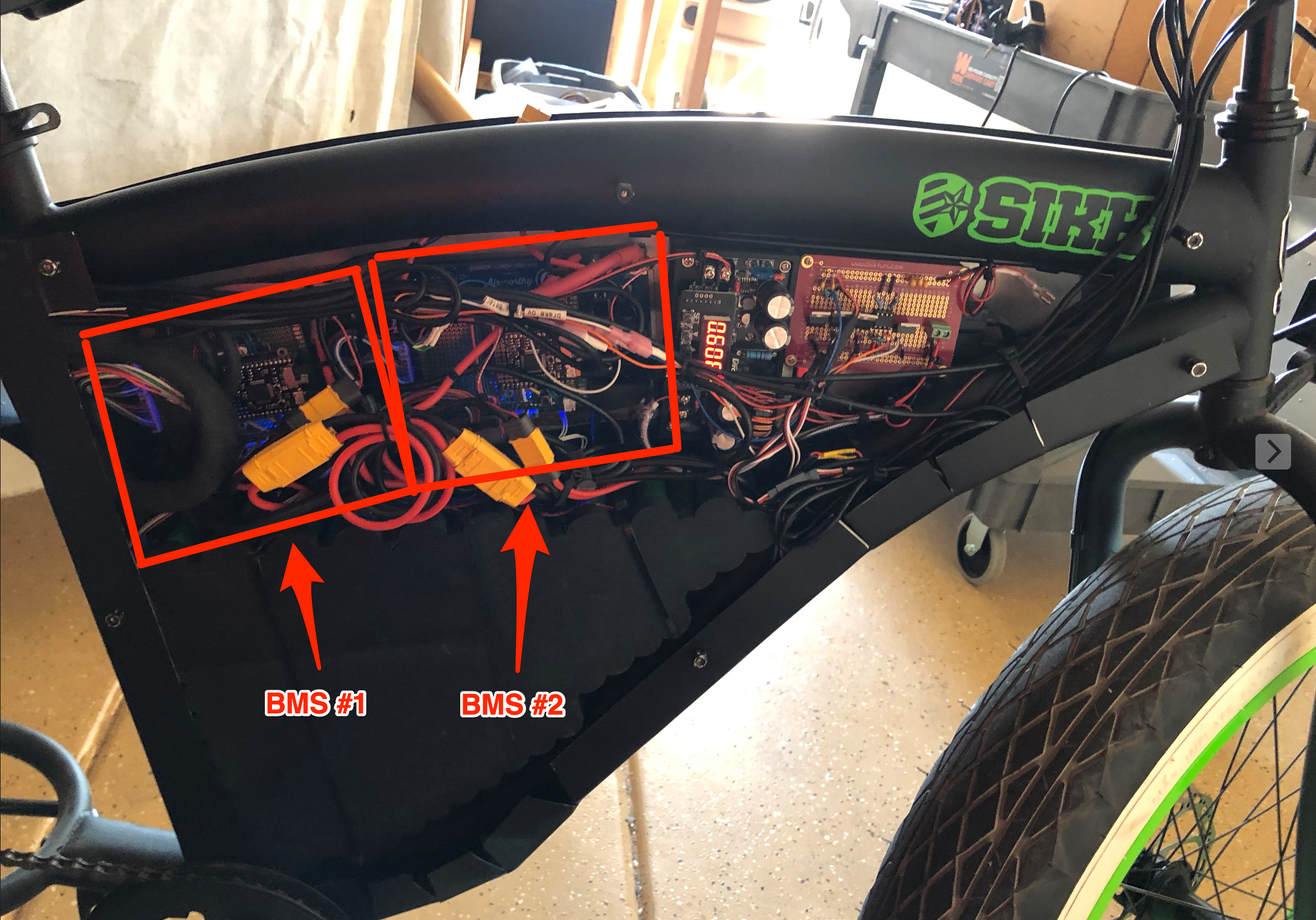
eBike BMS’s
They’re kinda buried beneath the wires in this picture, but you can make them out.
In this design, I did away with the OLED screen and rotary encode because there’s a RaspberryPi and touch screen that I’ll talk about in a later post.
Of note here is that the two BMS are working in parallel. They don’t know about each other yet they share all the connections to the rest of the bike. This demonstrated some interesting feedback problems. For example, at one point BMS #1 shutdown due to discharge over current. That left BMS #2 and it’s cells to do all the work powering the bike. It did fine but used up a bunch of juice in the process. When I realized that happened, I tried to turn BMS #1 on. But, it had a higher voltage than BMS #2 now and immediately started to charge BMS #2. Since there’s no resistance between the two BMS’s, the current skyrocketed and both BMS’s shutdown due to overcurrent. There was no way to turn them on anymore. They were locked in an death grip… until I charged them.
Some communication is needed between the BMS’s. In the case of the eBike, I took advantage of the RaspberryPi to mediate. The BMS’s were already talking to the RaspbeeryPI to report their status and voltages. By expanding the communication API the RaspberryPi is able to make sure both BMS’s play nice with each other.