Building a BMS
To summarize the 4 months since my last post: I’ve been educating myself. Primarily, my time has been spent learning how to build a BMS (Battery Management Sysytem). And there was a lot for me to learn.
There were several attempts at a BMS that I’d like to share with you.
1) Voltage Dividers
With Chuck Studee’s guidance, the first problem we wanted tackle was measuring the voltage of all the cells. Fortunately, the Arduino can sense voltage on one of its analog pins. It’s often referred to as an ADC (Analog to Digital Converter). It can measure up to 5V.
But here’s the rub. The pack has 10 cells in series, delivering 42V from Pack- to Pack+ when fully charged. There’s a lead from each cell’s + terminal and if we take a multimeter to each lead, from Pack-, we’ll read the following voltages down the line: 4.2, 8.4, 12.6, 16.8, 21, 25.2, 29.4, 33.6, 37.8, 42. Assuming we use Pack- as ground for the Arduino (otherwise we have floating voltages: bad), we can read the 4.2V from the first cell, but all the rest are too high!
Well, we can use Voltage Dividers to solve that problem. By connecting a voltage source to ground through two resistors in series, the voltage measured in between the two resistors will be divided according to this formula: Vout = Vin * R2 / (R1 + R2). So if we can divide our voltages by 10, then the max 42V turns into 4.2V. Nice! However, I didn’t have the resistors to divide by 10, so we divided by 11. R1 = 10k and R2 = 1k.
Easy, right? Well, problem is now we’ve got 11 leads from the battery pack, and not enough ADC pins on the Arduino. Ideally we use 1 ADC pin to measure all the voltages. So we use a multiplexer to programmatically choose which lead we want to read from. Except we need two multiplexers so that we can read the voltage between the leads on both sides of an individual cell. This give more precision. So then we need a Differential Amplifier. The outputs from that are small, so we use an Instrumental Amplifier to make the recision easier to read on the ADC pin.
But there’s more:
- A Differential Amplifier is use to measure the difference between the two leads we multiplex into it.
- A Instrumental Amplifier is then needed to precisely multiple the smal voltages we get from the Diff Amp.
- A Linear Voltage Converter is used to feed the ADC’s reference voltage down to ~4.2V.
- A Buck Converter is used to reduce the pack’s voltage to a nice 7V that the Arduino can use.
- Diodes protect the cell leads
- A OLED screen displays the readings
- A push button Rotary Enccoder allows user inputs
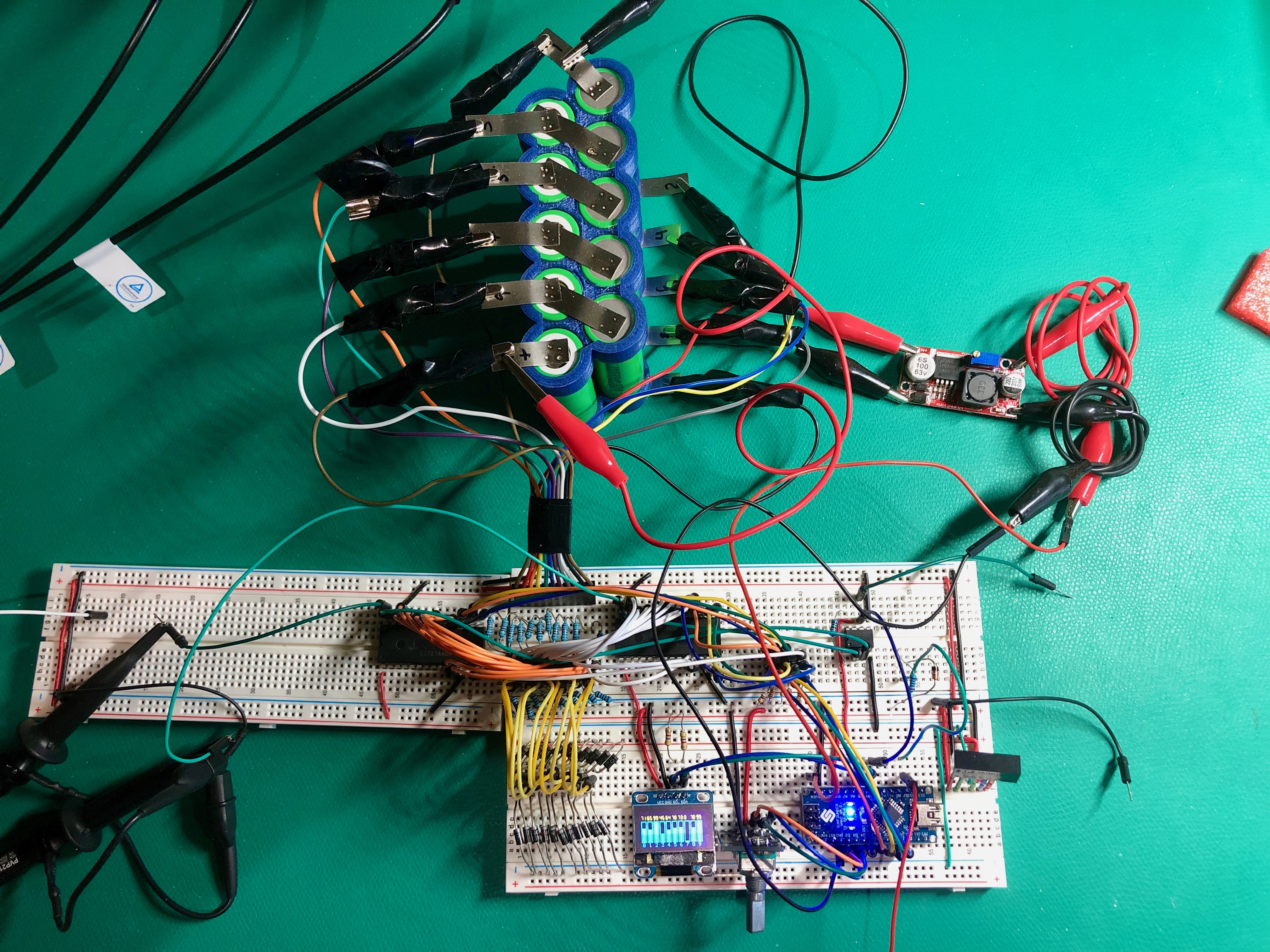
AND… IT WORKED! The circuit measured the voltage of each cell with relatively good accuracy. Nice. And then I thought “How do we balance cells now?”.
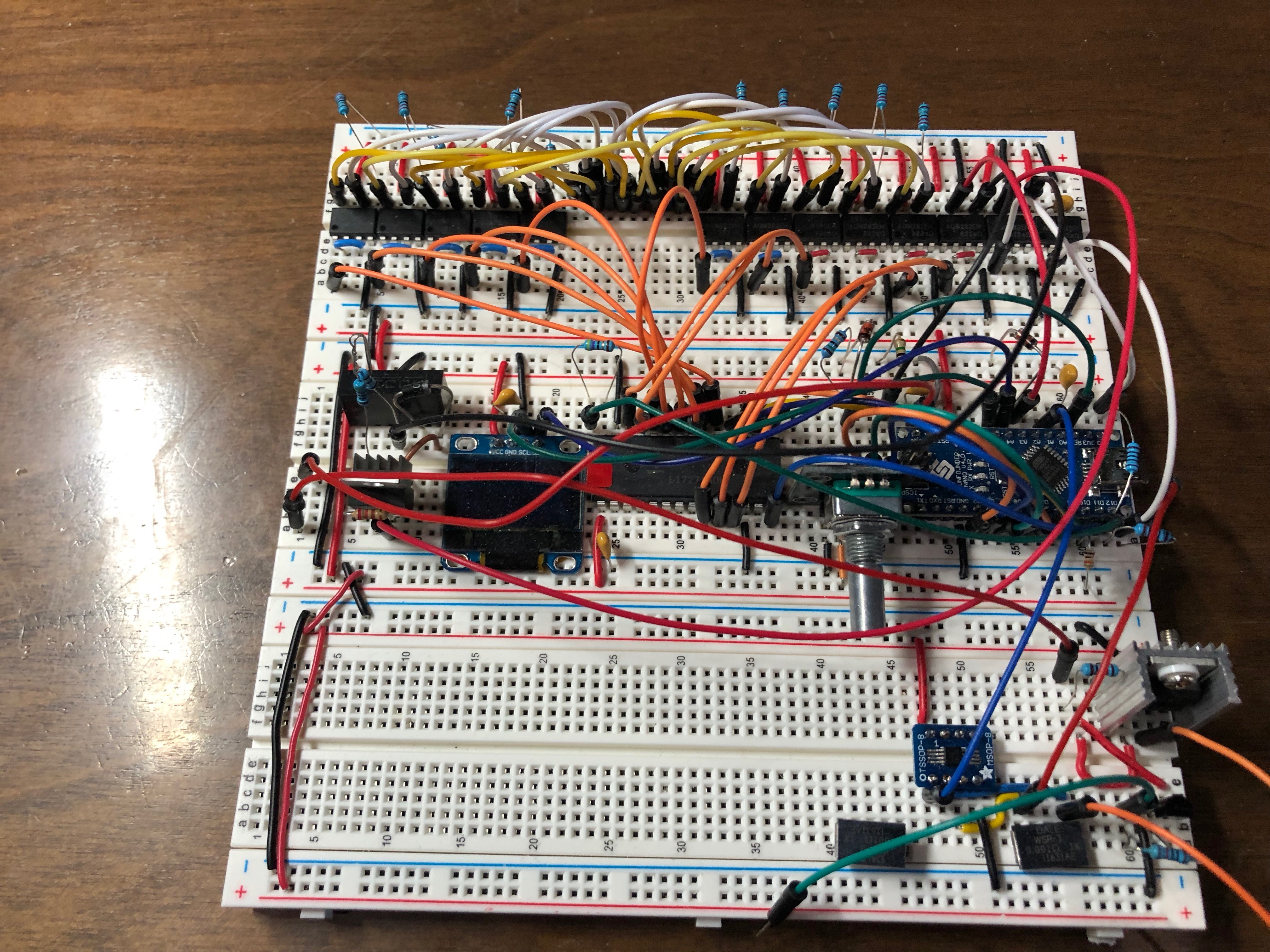
2) Flying Capacitor
That first circuit allowed no means to balance cells. And along the way, I read about a “Flying Capacitor” technique I wanted to try. The principle is that you connect both leads of a single cell to a capacitor, charge the capacitor, then disconnect. The capacitor now holds the voltage of the cell. You can then connect the capacitor to the ADC (and ground) to read the cell’s voltage. Or, you could connect that charged capacitor up to a power resistor and effectively drain the cell. Or, you could charge the capacitor with a full cell, and then connect it to a less full cell. Either way, this Flying Capacitor solves the problem of voltage measuring and balancing.
The problem with this technique is that all the connections to the Flying Capacitor needs to be isolated. If any of the components get connected to the capacitor at the same time, or if they happen to share a ground at some point, they fry. I have a bin of burnt parts to prove it. To isolate the circuits I used a device called an Opto-Fet or Photo-MOS. It has four leads with an LED embedded in the chip. When the LED is powered, the other two leads are connected. Both sides of the opto-fet are totally isolated from each other.
With a fleet of these opto-fets, the circuit was able to measure voltage accurately, but the rate of balancing was abysmal. It turns out that charging and discharging a capacitor over and over is not very efficient.
3) BMS Chip
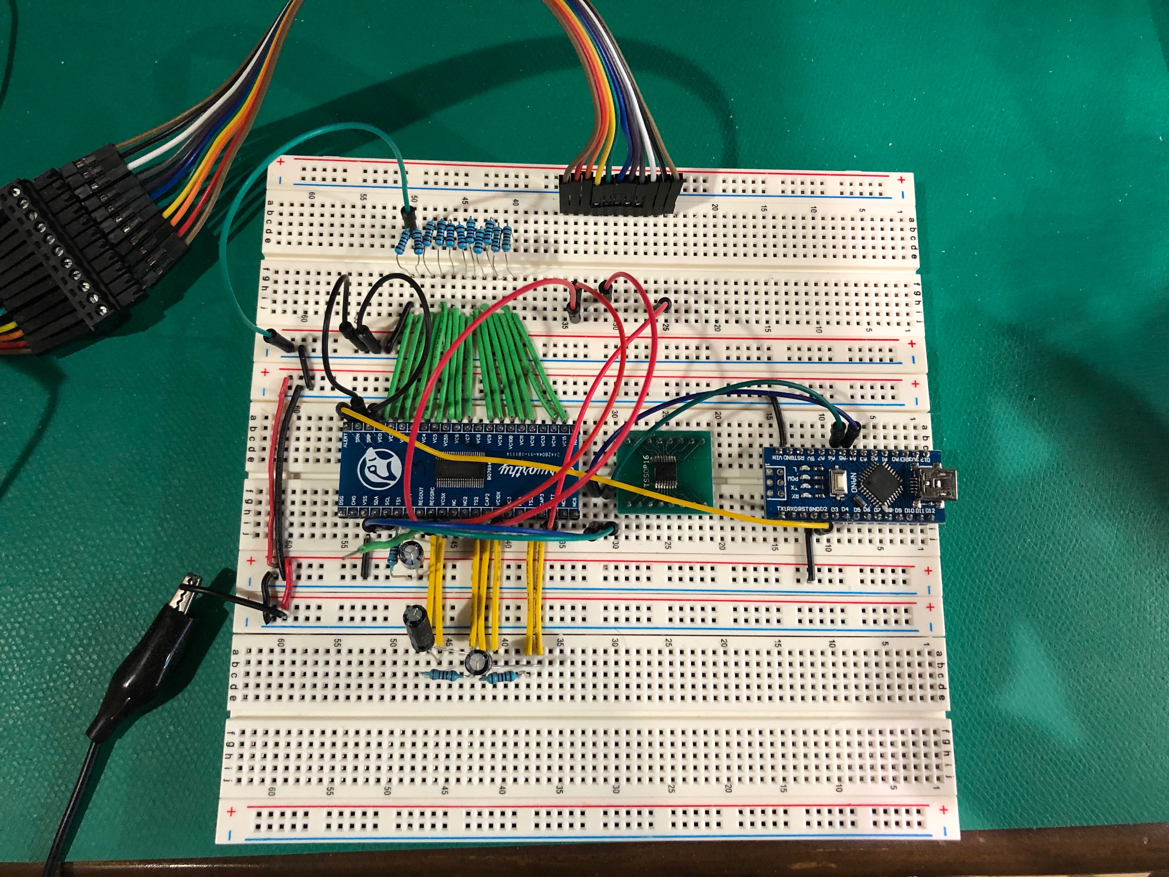
The BMS problem has been solved before. Texas Instruments offers an amazing chip that does everything I was trying to do and more in a package smaller than a dime. The BQ76940. I ordered an evaluation kit and started playing with it. It worked great! So I started to build a circuit on a breadboard using this chip. I even designed a little PCB (printed circuit board) to adapt this surface mounted chip to 2.54mm pins.
My breadboard circuit was working somewhat, but only after wiring up almost all of the 44 pins on the BQ76940. The circuit had become overwhelming for a breadboard.
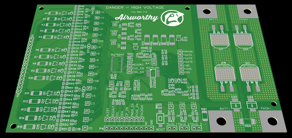
4) PCB
Based on the forum posts, I felt like the only fool to try and wire up the BQ76940 on a breadboard. I bit the bullet and started designing my own PCB. This was a week long adventure and I feel good about the result. The PCB is currently being fabricated and all the surface mounted chips are on order.