eBike: Milled Circuit Board
The eBike is controlled with a Raspberry Pi, which will be the topic of a later post. Here’s I’d like to discuss circuit board through which the Raspberry Pi manages all the hardware on the bike. The hardware features include:
- Headlights
- Tail Light
- Brake Light
- Brake Cutoff
- Ignition
- Power Up
- Speedometer / Odometer
Circuit Board Evolution
Here’s the original prototype that was assembled piecemeal as the bike evolved. The protoboard worked great but got quite crowded toward the end.
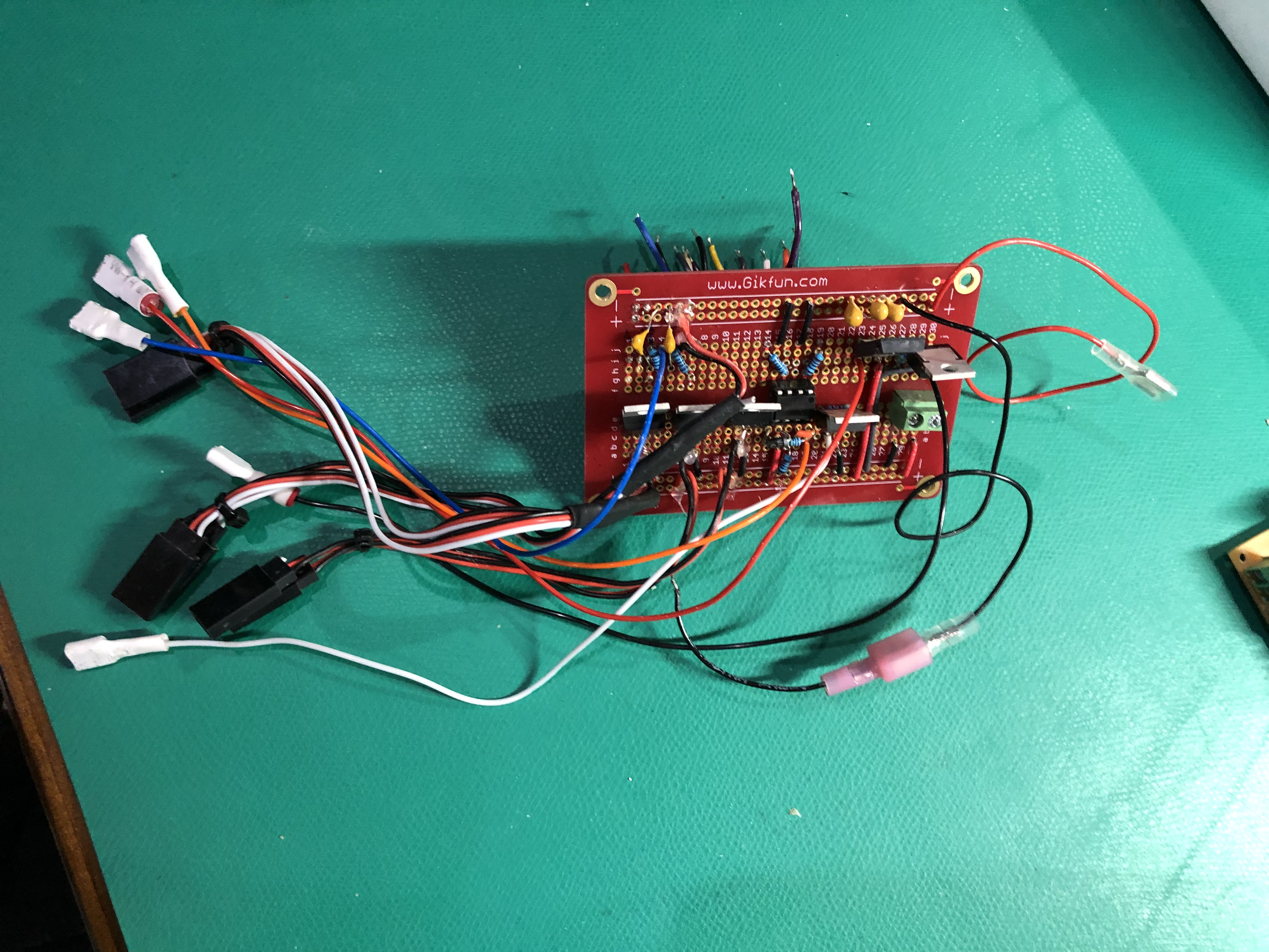
What a mess, eh? With the circuit fully fleshed out, it was time to create a more permanent solution.
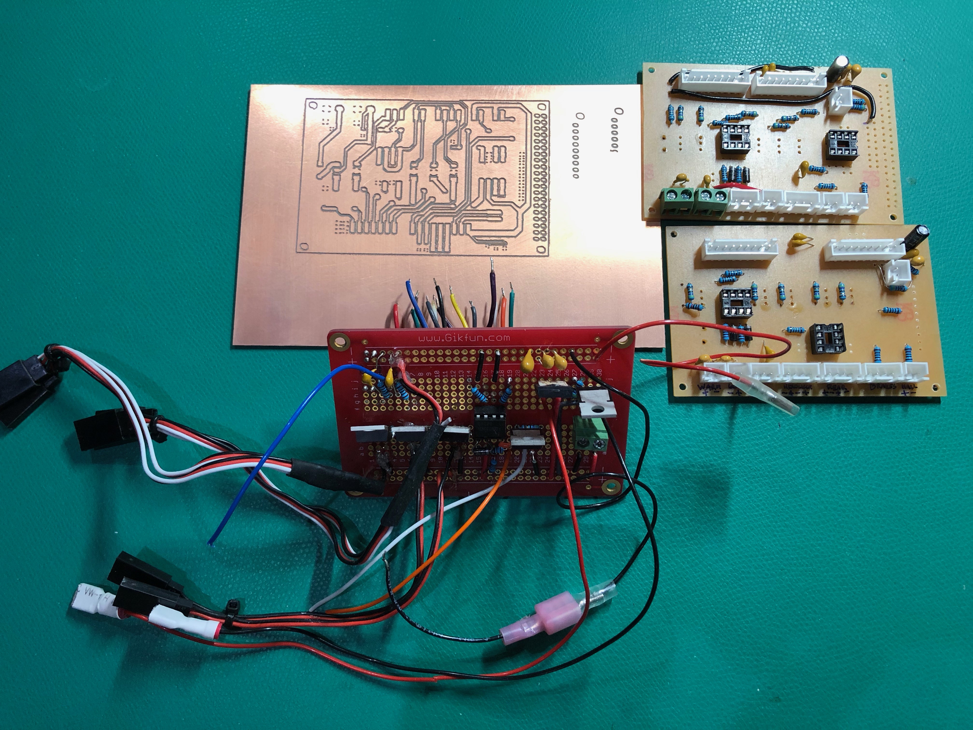
In total there were 5 attempts to get a finished product. Here’s the graveyard of failed and obsolete boards.
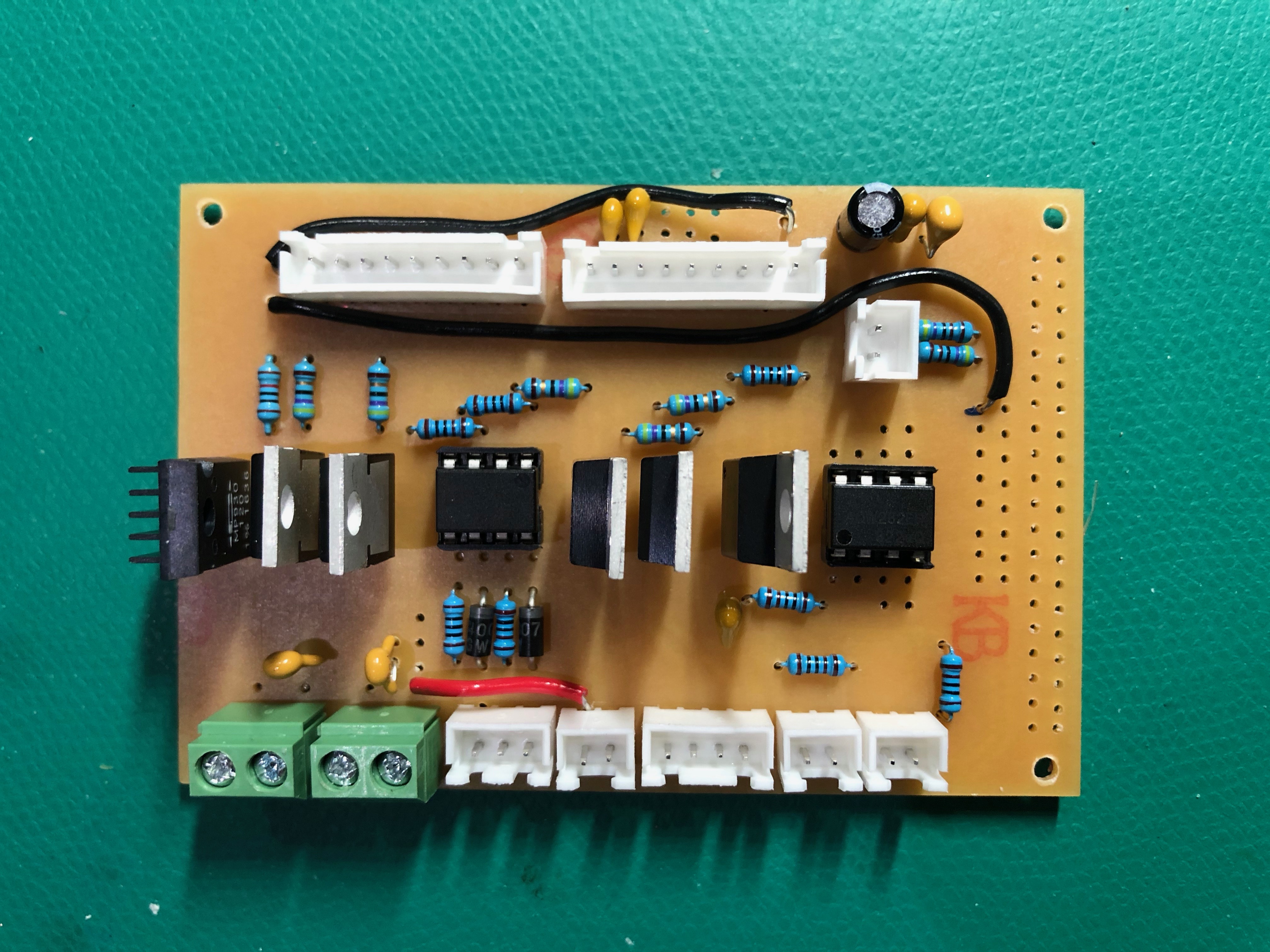
A closeup of the populated board:
The 5th version is currently on the bike. Truth be told, there will likely be a 6th version because I still had to hack the 5th to get it working right.
MCB - Milled Circuit Board
With the BMS circuit board, I sent my design to JLCPCB which is a great Printed Circuit Board (PCB) manufacturer. The quality of their boards are very high at a great price! Sadly, it takes a week for them to manufacture the boards and for the shipping company to deliver them. And you have to order multiple boards.
This eBike board is a one-off. And I didn’t want to wait a week. So I tried a technique I saw on Youtube: Milled Circuit Boards. The design process is mostly the same as for PCBs. EasyEDA is my tool if choice for designing circuit boards. Finished designs come in the form of “Gerber” files. These are what you give the manufactures. However, for this board I needed to convert the Gerber files into a format that I could use on my Shapeoko CNC Router. FlatCAM is open source desktop software specifically made to convert Gerber files into GCode (CNC language). It did the trick.
Watching the CNC machine work on these circuit boards is mesmerizing. I took a video that you can watch below. NOISE ALERT! You might want to turn down your speaker before playing.
General Architecture
Now for the nitty-gritty. You can stop reading unless you’re into electrical circuit design.
The board has two power rails, 3.3V provided by the Raspberry Pi, and ~60V that comes from the batteries. Both rails have a common ground.
Lights
Controlling the Headlights, Tail Light, and Brake Light is straight forward. All three lights are LED’s that run off 60V. I had ordered some high voltage logic level N-channel power MOSFETS. The 3.3V from the Raspberry Pi is sufficient to drive the Gate pin of the FETs. The Source pin is connected to ground and the Drain is connected to the cathode of the LEDs. Easy.
Brake Cutoff
The Brake Cutoff is a safety feature of the ESC (Electronic Speed Controller) that prevents the rider from applying both the brakes and accelerator at the same time. The ESC has a Brake Cutoff wire that should go to ground when brakes are applied. In most bikes, this wire is connected directly to the brake handles which have an internal switch that closes when you apply them. However, I need the Brake Light to turn on when brakes are applied, so the simple solution doesn’t work.
My brakes are connected the the 3.3V rail and an a GPIO pin of the Raspberry Pi. When brakes are applied, the GPIO pin goes HIGH and the software detects this. The Brake Light is turned on and another MOSFET is turned on to connect the Brake Cuttoff wire to ground.
Ignition
Another wire exposed by the ESC, the Ignition, is typically connected to an ignition key that switches the battery voltage. No significant power is drawn through this wire. It’s simply a signal to tell the ESC that the bike has been turned on.
No key for me. Instead my bike uses a key pad on the touch screen. When the correct code is entered, the Ignition is turned on.
The simple N-Channel MOSFET trick won’t work to connect the ESC’s Ignition wire to 60V. It would require a charge pump or something to bring the Gate to ~63V. Parts I didn’t have. What I did have was opto FETs; solid-state relays where one side is an LED that turns on a FET bridging the other side. And to my luck, they are rated for 60V. Win!
When the secret code is entered, the Raspberry Pi brings a GPIO HIGH to turn on the opto FET. The other side of the FET bridges 60V with the Ignition wire. Now, when I measured the current drawn by the Ignition wire, I read 50 mA. The opto FETs are rated for 100mA so all’s good. But there must be a current spike because the opto FET got fried. A current limiting resistor, protection diode, and a new opto FET played together nicely.
Then I noticed that the ignition stayed on, even when the Raspberry PI pulls the pin LOW. Maybe it was intern capacitance of the opto FET, or some mystery of the ESC internals. Either way I couldn’t let the Ignition stay ON for some unkown duration. So using another opto FET I bring the Ignition wire to ground momentarily, and then it stays there.
Power Up
Another divergence from typical bike design is that I wanted my batteries TOTALLY disconnected from the motor when the bike is not in use. The problem here is that the ESC has some hefty capacitors that love to charge up quick when connected to power. You can see the spark when the ESC is first connected to batteries.
When the Raspberry Pi unlocks the bike, after the secret code is entered, the first thing it does is turn on the batteries. If the bike has been sitting for a while, those hungry capacitors in the ESC are just waiting to chug some juice, and when the batteries are turned on the caps do chug, fast! Current coming out the batteries sky rockets and the BMS kicks in shutting down the battery; Discharge Overcurrent.
What’s needed is a “warm up” circuit. Something that feeds those caps at a slow rate until they’re full enough that the batteries can safely be turned on. So I measured the ESC capacitance, 4mF, and did some math.
- t = RC, 2*t give 95% charge and I’d like that to be 1 sec or less, so t = 0.5.
- 0.5 = R * 0.004 ===> R = 125. We’ll round it down to 120 ohms. Now how much power is going through that resistor?
- P = V^2/R ===> 30W. Wow. That’s a lot of power. It means I need to order special power resistors.
How to power this “warm up” circuit with out turning the batteries on? Well, I tapped that batteries directly, bypassing the BMS, to created an isolated 60V rail on the circuit board. It’s not ideal, but for this project we’ll let it slide.
The positive sides of the “warm up” 60 V and normal 60V rails are linked through the 120 ohm power resistor. But the grounds goes through another N-channel MOSFET. When the N-FET is turned on the normal 60V rail is powered, limited by the resistor, and the ESC caps charge up for 1 second. Then the N-FET is turned off and the batteries are turned on, without any Overcurrent.
Since the N-FET is on an isolated ground, the Gate can’t be driven by the Raspberry Pi. The Gate needs to be driven from the isolated “warm up” power. Hmm… Well the Raspberry Pi can turn on an opto FET. And resistors can divide the “warm up”’s 60V down to 5V to drive the Gate. So there you have it.
Speedometer / Odometer
The wheels on the bike go round and round. Given the diameter of the tire and the interval between rotations, calculating speed and distance is easy.
There is a “Hall” wire exposed by the ESC that is undocumented. Using my scope I learned that it produces a 3V square wave of 16 periods for each revolution of the tire. By using a GPIO pin on the Raspberry Pi, I was able to detect the rises of the square wave and use that to calculate speed and distance.
There were just two problems.
1) The Hall wire actually peaked at 5V, though only in very short spikes. Three pins on the Raspberry Pi got fried before I figured this out. The fix was to use another opto FET. The Hall wire turns it on with 5V. The Raspberry Pi powers the other side with 3.3V.
2) EMI - Electro-Magnetic Interference. The ESC inverts the DC current into AC at a high rate to drive the motor. This produces EMI all over the circuit that can be seen on the scope as tiny spikes in voltage, dozens a second. The Raspberry Pi pin to sees these as dozens of rises each second, even if the tire isn’t moving. Although this problem vexed me for days, the solution was simple. A 100nF capacitor across the pin and ground did the trick.
Originally, I ordered a Reed switch (a switch that reacts to magnets) that I would install on the front tire. But I was intrigued by the Hall wire and the simplicity it would add to the overall design. But I’ll freely admist that the Speedometer and Odometer are not 100% reliable due to the problems mentioned above. Now I’m inclined to install that reed switch and be done with the Hall meter mess.