NiteLite
A while back I modernized an old-school arcade that came with our house. I was running Windows 98 on a tower PC and a fat CRT monitor. I cut about 2’ off the back of the 7’ tall box, replaced the monster CRT with a flat LCD screen, replaced the big tower PC with a credit card sized Raspberry Pi, and installed RetroPi along with classic Commodore 64, Nintendo, and arcade games. It’s much nicer to use now.
The cherry on top was an Color LED strip to make it glow against the wall. Check it out!
Controlling LED Strips
The point of that story is that I was left with an extra strip of LEDs and no control box or remote to power it. So one day I wired it up to an Arduino to figure out how it works. It’s rather simple. There are four leads or “pins”: 12V in, R(ed), G(reen), B(lue). Obviously the 12V pin gets connected to a 12V power supply. When the R, G, or B pins are connected to ground, the LEDs light up in the corresponding color. If they all get connected to ground, the LEDs glow bright white. But I wondered: How does that control box get the LEDs to fade in and out with variable brightness?
Here’s how I did it. With the LEDs’s RGB pins connected to ground through an NPN transistor, the Arduino can turn the LEDs on by putting 5V on the transistor Base. Even better, the Arduino has a few PWM (Pulse Width Modulation) pins. They basically turn on and off really fast and you can code the percentage of time they are ON. Using PWM pins the Arduino can turn the LEDs ON and OFF really fast and control the percentage of time they are ON. Did I mention the PWM is fast? It is. Faster than the eye can see. So by setting the PWM pins to a low value, the LEDs glow faintly, and with the PWM set to a high value, they glow bright. Cool!
Well, I thought, “There’s gotta be something I can build with that.” After Googling I found an idea. My 8yo son Tristan has a clunky night light globe that he turns on every night. It has a static glow pattern in 3 different colors and rotates with a rattling noise that makes you think it’s going to fall apart any minute. My plan was to build Tristan a much cooler night light.
The new and improved night light, code named “NiteLite”, would have a strip of LED’s lighting up a glass carving that would glow in a elegant and soothing manner. An Arduino would control the colors and brightness of the LEDs. And why not put some knobs to allow Tristan to change the color and brightness to any of thousands of possibilities? To make it even more fun, NiteLite will have a couple buttons that’ll let you cycle through various modes. Each mode will make the colors dance, fade, and entertaining in various ways.
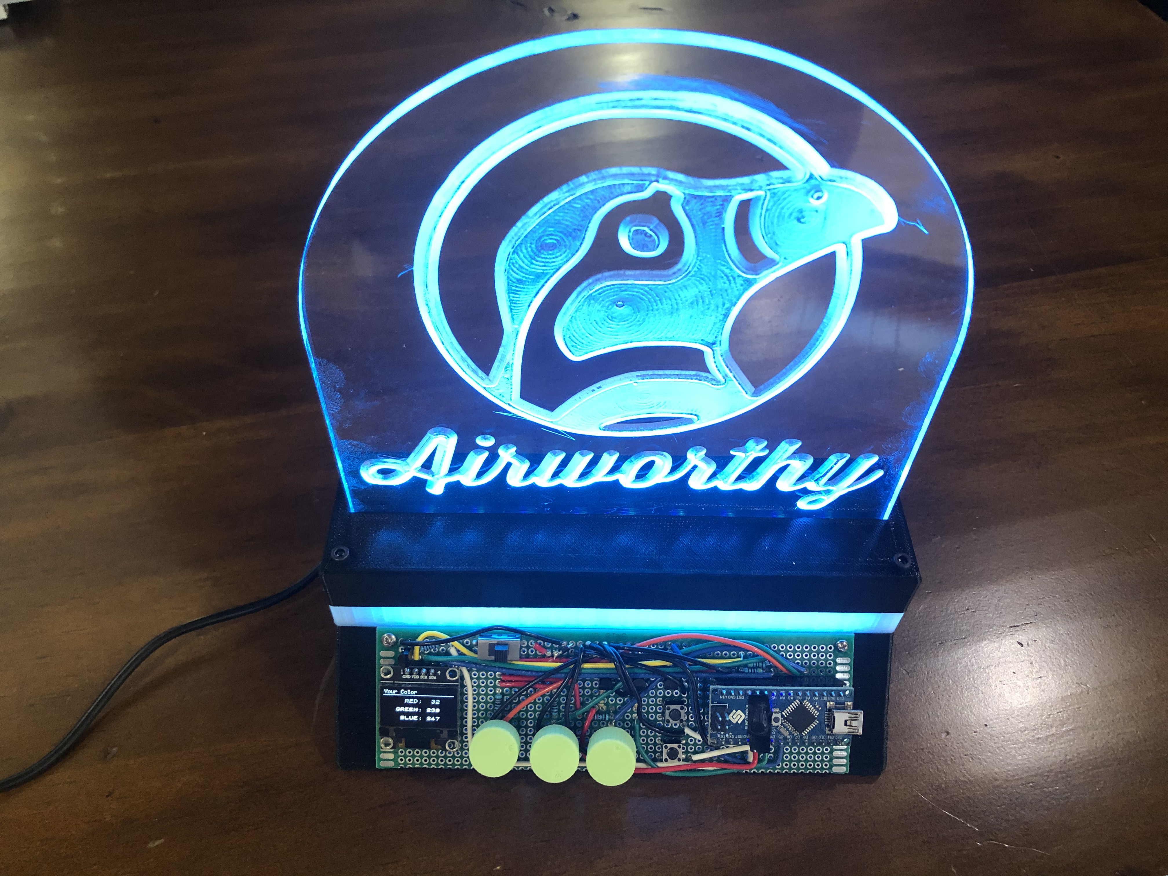
After some tinkering, I completed a prototype:
3D Printing
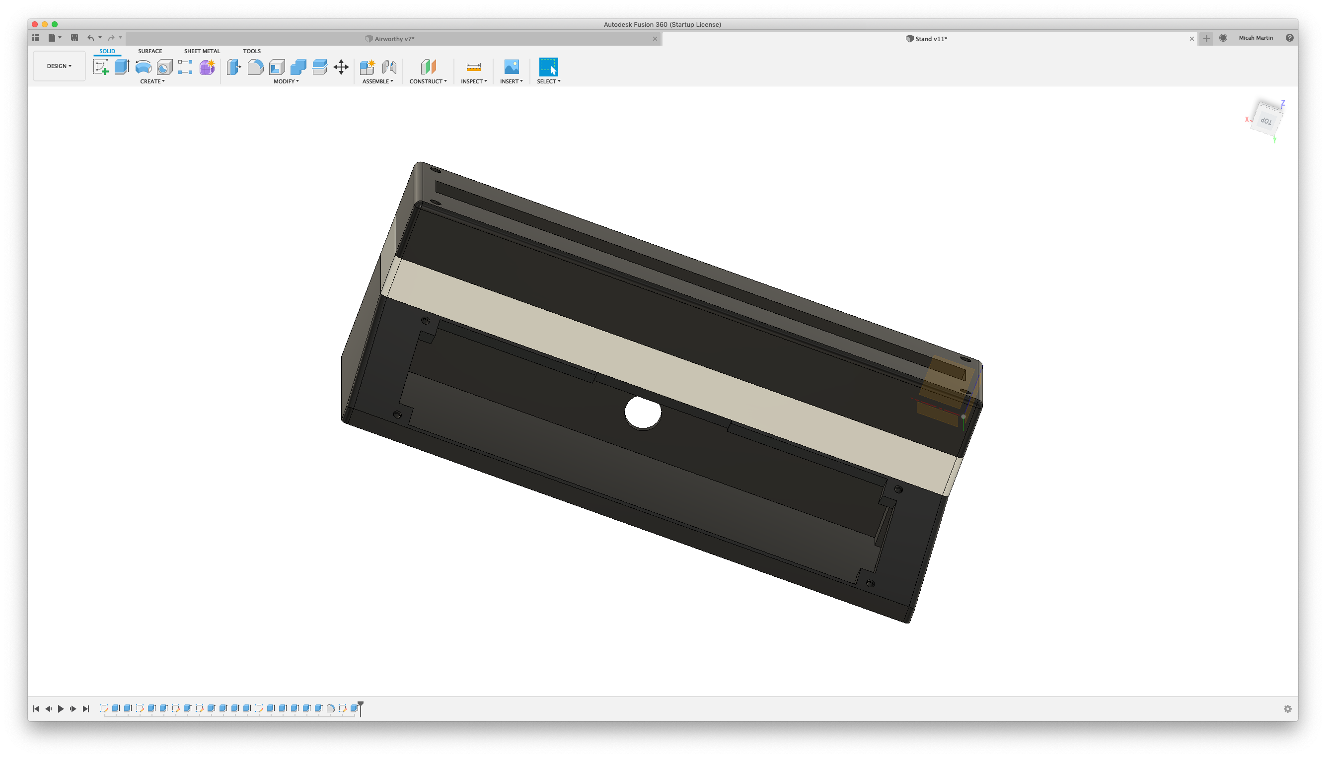
The base of the NiteLite needs to A) hold up the glass carving, and B) encase the electronics. It occurred to me that I have some “transparent” (more like translucent) PLA that could be used to get the base to glow a bit too. So I designed a 3 part base that you can see below. The top section holds the glass. The middle section uses the clear PLA for a glowing layer. And the base will hold the electronics.
Although I originally planned to hide all the circuitry inside the base, I rather like the look of circuit boards. It’s probably just me but circuit boards are cool and keeping it all exposed adds character and intrigue.
Acrylic CNC
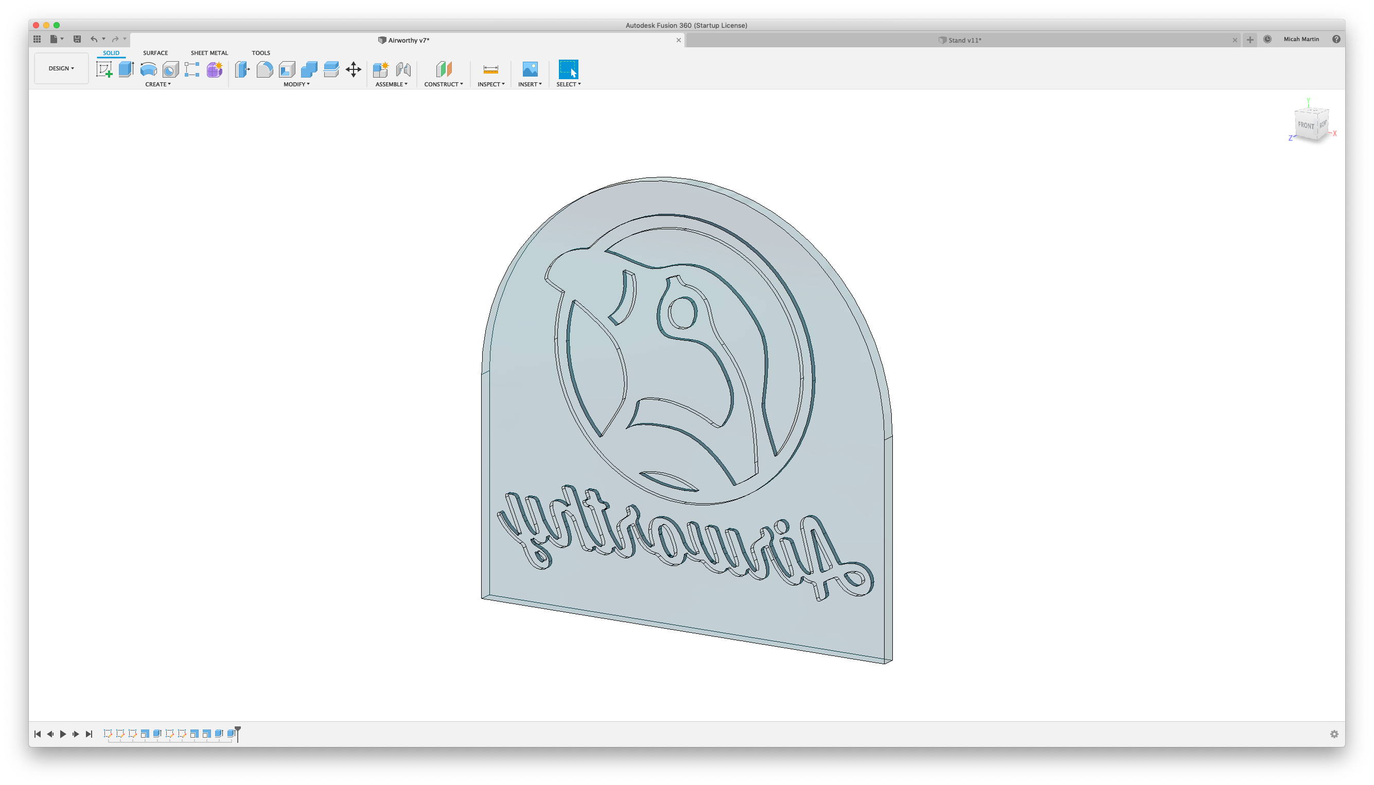
I wanted to use my CNC router to carve the glass although I wasn’t going to carve real glass… that’s just scary. So I went to the hardware store to look for some clear plastic. What I found was a nice sheet of acrylic.
Using Fusion 360 I designed a… well… I’ll call it a “glow plate”. Fusion can import SVG images so for the prototype I just used some Airworthy SVG files that I had on my computer. I took my design out to the CNC machine and… machined it. It looked terrible. I didn’t know what I was doing. And unfortunately, there aren’t any good tutorials about CNC’ing acrylic online. So I had to play around, do some trial and error. Eventually I found techniques in CAD, CAM, and CNC that resulted in a decent looking glow plate.
In my research I leaned that there are two types of acrylic: extruded and cast. What I had picked up from the hardware store was extruded acrylic. It’s of lesser quality and I felt that may have caused some of the imperfections in my work. It was also quite thin at 5mm. This is the material used in the prototype image above.
On McMaster-Carr I found some cast acrylic stock and ordered a 13mm wide sheet. The result of CNC’ing the cast acrylic was quite a bit nicer and I’m fond of the beefy thickness.
Circuitry
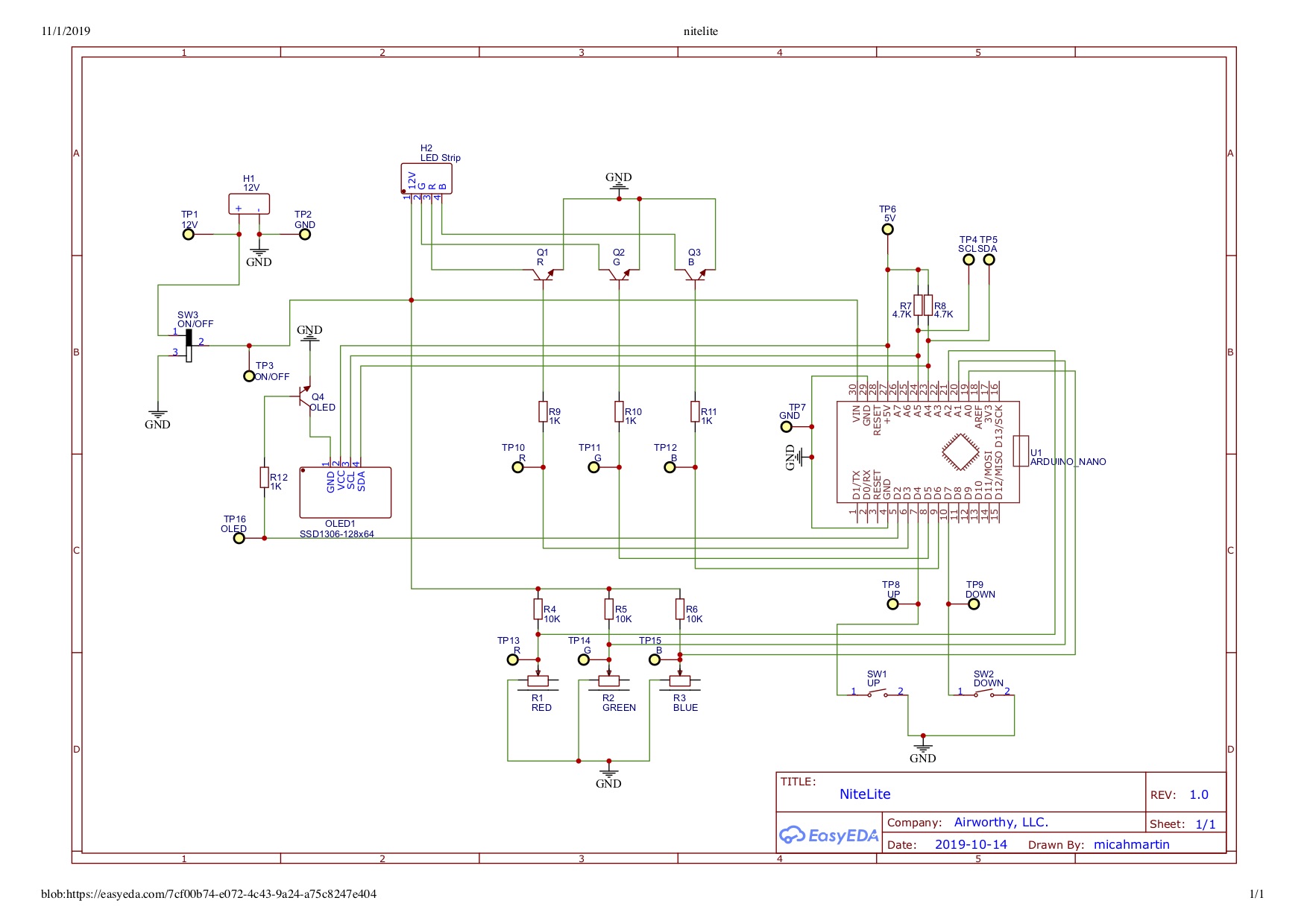
I designed the NiteLite circuit schematic in EasyEDA. Compared to previous circuits I’ve designed, this one is pleasantly simple.
- 1 Arduino, the brains of the outfit
- 1 OLED screen to display color levels and mode.
- 4 NPN transistors, 3 to control the RGB LED pins and 1 to turn the OLED screen on and off.
- 3 5k potentiometers as knobs to control color brightness
- 2 tactile switches, the buttons to navigate modes
- 1 on/off switch for the 12V power
- 3 10K resistors to work in combination with the potentiometers to divide the 12V down to <5V for the Aurduino anlalog input pins
- 2 4.7k resistors as pullups for I2C comm between Arduino and OLED screen.
- 4 1k resistors to limit current to the transistor bases.
On the prototype, I wired up through-pin components onto a proto-board. This was time consuming and did not produce the most aesthetic circuit board as you can see in the prototype image above. For the final product I designed a PCB (printed circuit board) and ordered surface-mount components and better through-hole components. See below.
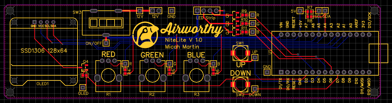
I ordered these in a black finish. See how nice it looks in the last image below.
Source Code
On the Arduino you can choose which every programming language you like, so long as it’s C++. Urg! Coding in C++ is a drag.
The code base is available on Github. It was developed using TDD (Test Driven Design) so all the code is tested, except for the thin layer that interfaces directly with the Arduino hardware.
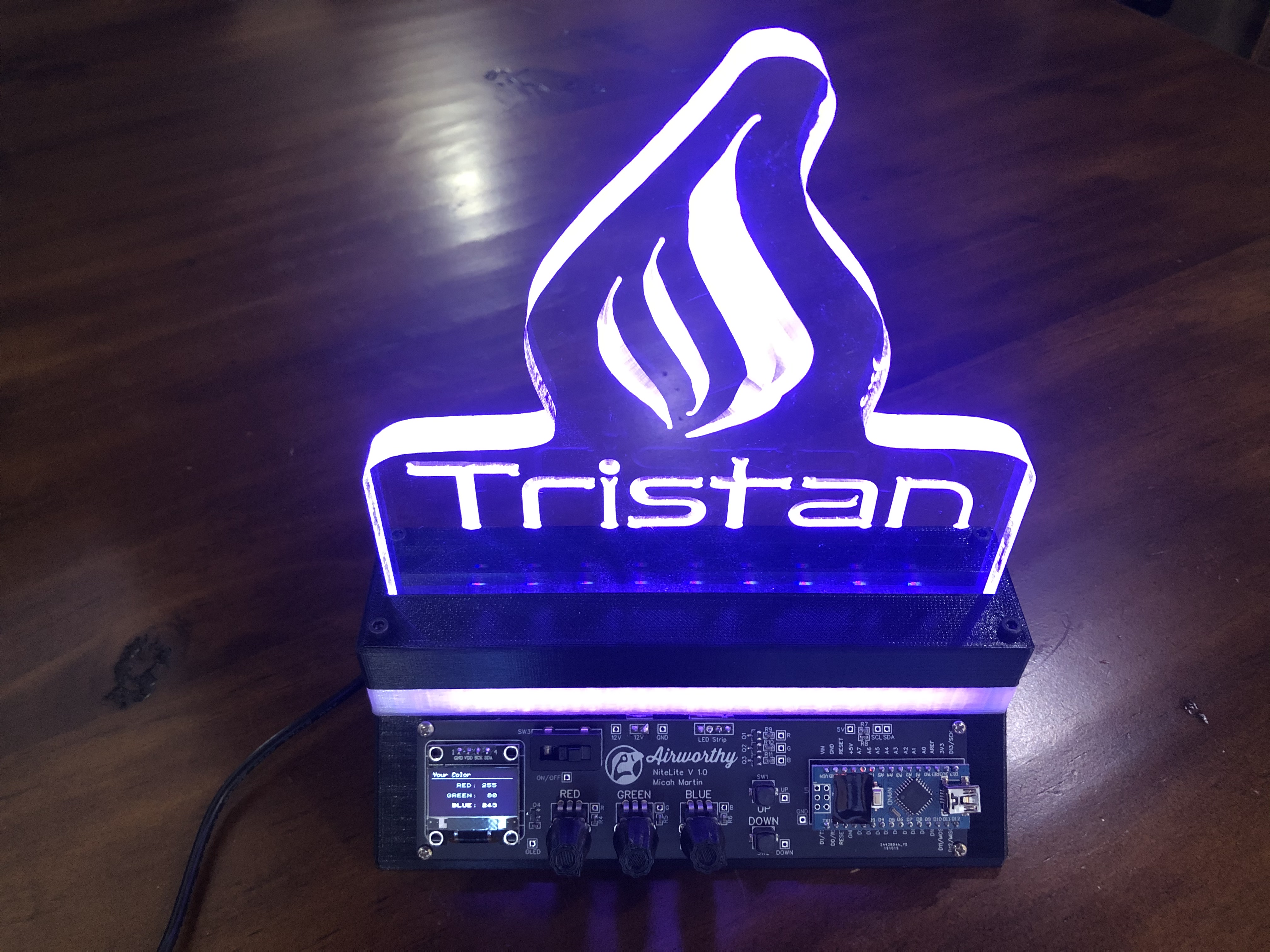
Tristan’s NiteLite
Yesterday, Tristan and I worked on a design for his NiteLite. He chose the font used on his name and after exploring many options for decorating it, he settled on a symbolic flame. I printed the base, CNC’ed the glow plate, and put it all together today while he’s at school. It’s on his night stand waiting for him to find it when he gets home. I think he’ll like it.