Scooter Batteries
My Brother Justin, recently purchased a used electric scooter, or more like a moped. Unfortunately, the battery pack in the scooter died shortly after the purchase and Justin was left without transportation. How sad.
Fortunately, I had a pile of fresh 18650 cells along with my new BMS design. So I offered to build him a new pack and in exchange he would share the data generated by the BMS/Batteries that’s I’d build. It was a great opportunity test my equipment and learn more about electric vehicles.
Requirements
Since this is was meant to be a drop-in solution, I’d have to build packs with the same characteristics as his dead pack.
- Voltage: 72V
- Current: 130A
My BMS can only handle 15 cells in series. At 3.6V each, a single BMS can only deliver 54V nominal. That means I’d have to build two packs and wire them up in series on the scooter. Each pack would have 10 cells in series delivering 36V.
The MJ1 cells are rated for 10A max. To achieve 130A, 13 cells in parallel are needed.
That’s 2 packs of 10s13p configuration. 130 cells each. 260 cells total. That’s about 3.3kWh of energy.
Bus Bars
130A is way more than I’d every dealt with before. The skateboard was a 30A system and I had to stack nickel strips to safely handle that meager current. Stacking enough nickel strips to handle 130A seemed like a shoddy solution. Instead, I headed over to the local metal supply store and purchased some 6mm thick copper sheet metal.
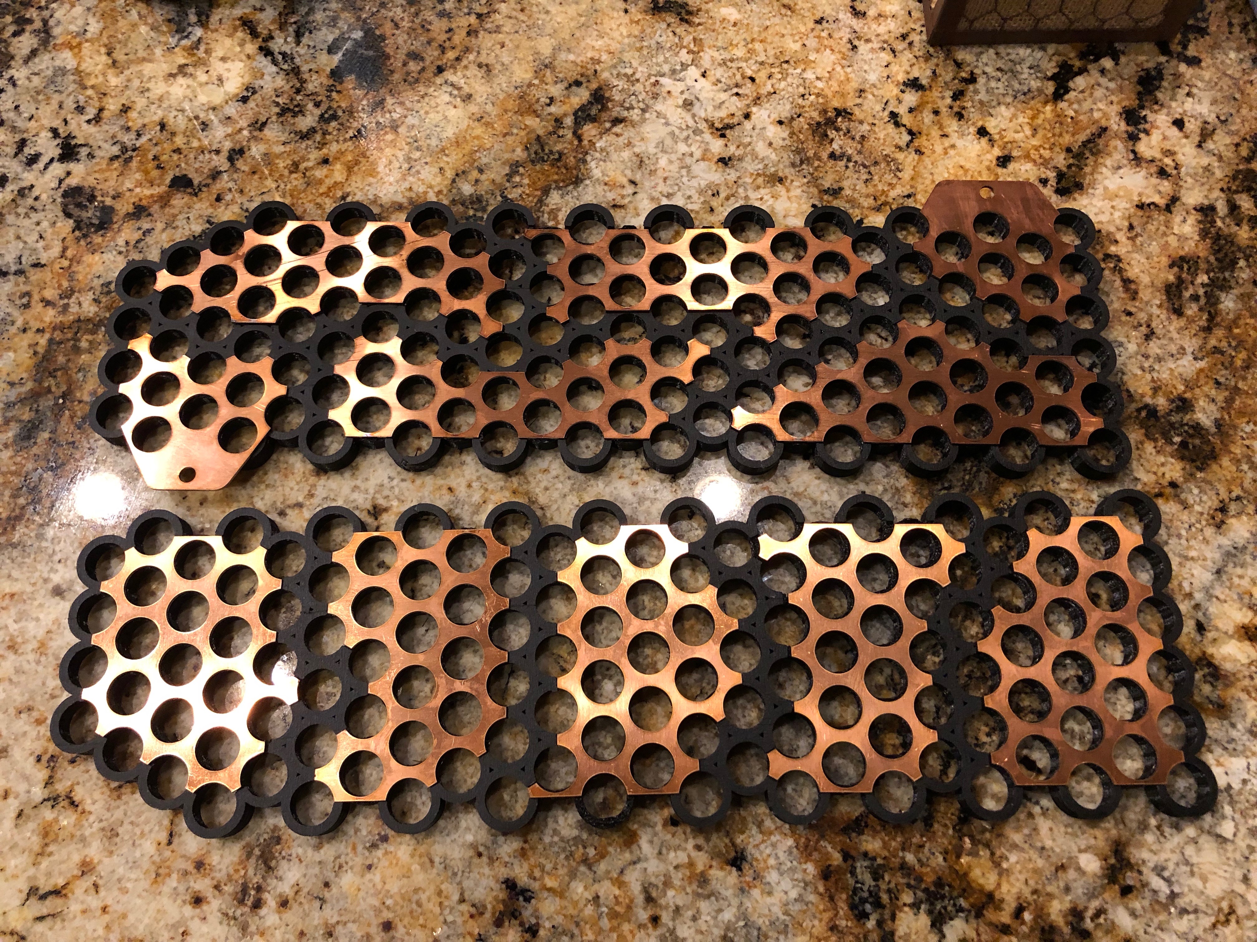
In Fusion 360, I modeled the packs along with bus bars to connect the cells in the 10s13p configuration. The question was, “How am I gonna cut that thick copper into the detailed CAD shapes?”
I called a few machine shops and drove my copper over. The guys at SteelCrest were great! They welcomed my in and conveniently cut my parts on the spot with their fiber laser cutter. What a beast of a machine! Check out the video below while my copper parts are laset cut.
Here’s the freshly cut bus bars fitting perfectly in the 3D printed cases I made.
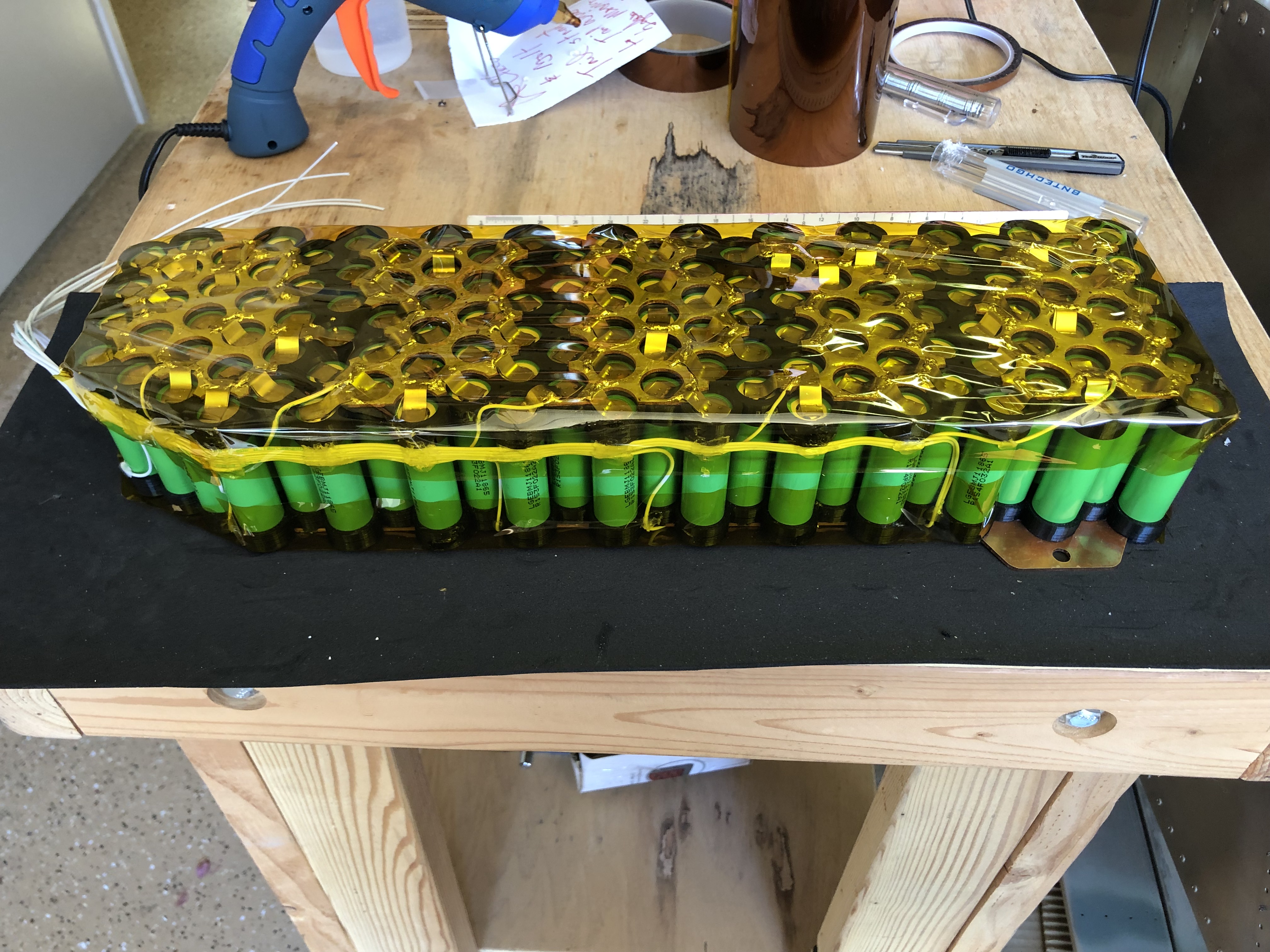
Welding
As it turns out, copper was not the best choice of material for the bus bars. Why? Because nickel doesn’t weld to copper, at least not with the spot welder I have. Nickel is needed to connect the individual cells.
I ended up plating the copper with solder. Spot welding the nickel to the solder did work, kinda. In the end I reinforced the spot welds with some solder welds (only on the bus bars so as not to heat the cells). The whole process made for lots of extra work. But it should easily handle the 130A and then some!
Fallen Soldier
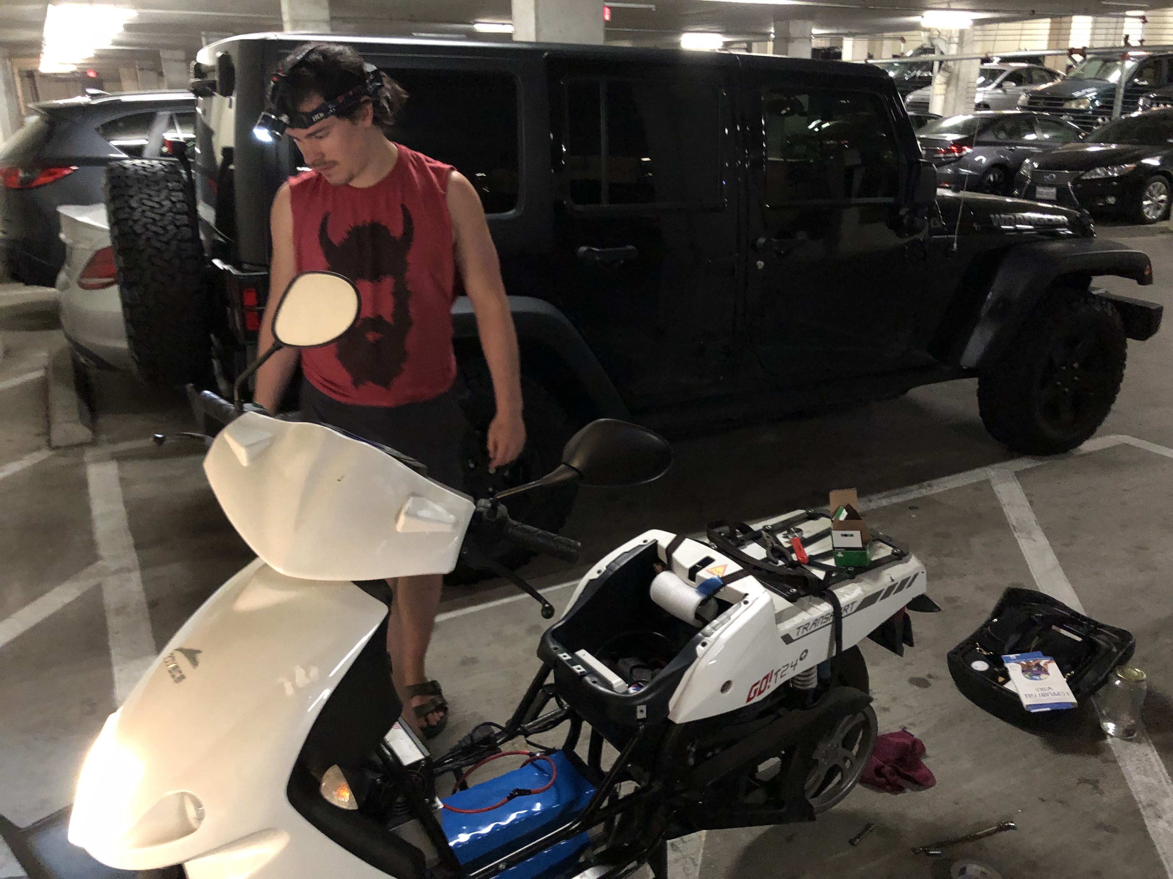
In the picture below, Justin and I installed new cells in his scooter. My two packs consumed significantly less volume than the previous pack.
Removing the original pack was by far the hardest part of the job. Is was NOT meant to come out. We had to disassemble most of the bike and use 2x4’s as crowbars to force the pack out.
Meanwhile, I had placed the new packs on the luggage rack of the scooter. That was hollow headed. As we yanked and cranked to get the old pack out, my new packs fell to the concrete floor. Wince. I tested the voltage and all seemed well. It wasn’t. A week later Justin measured the voltage again and it was low. 3.6V low.
One of the cells took the brunt of the fall and shorted internally. Not enough to explode or burn or even notice at first. But it was enough to drain itself and the other 12 cells in it’s group. There was little do do about it. I built Justin another pack to replace it.
This is the type of problem that cell-level fuses would have prevented.
Accidental Arc Welding
We wired up the BMS, connected ground to the scooter’s steele chassis, and then there was just the positive lead to connect. Justin’s fiance Ela (who is now is wife) just arrived and I remarked to them, “This is where it get’s interesting.” In my experience, motor controllers have beefy capacitors and when you close the circuit, there’s an frightening arc of glowing electrons.
At arm’s length I gingerly touched the positive lead of the controller to the corresponding lead on the BMS expecting sparks. But nothing! “Cool!”, I said as I relaxed, not realizing that my uninsulated connector was inches from touching the chassis. That is until it did touch.
72 volts with virtually no impedance except the steel chassis. SPARKS EVERYWHERE!!! Blinding light! Crackling thunder! I jumped back, as did Justin and Ela. Thank goodness the cable was loose and the circuit opened once I let go of it. The steel tubing had melted and a coin sized gouge was left behind. Not enough structural damage to warrant repair though.
Results
The Good News
The packs worked! Justin was on the road again, cruising the streets of Austin.
Before, Justin was lucky to get 20 miles on the scooter before a recharge was needed. With the new packs, he estimates he could go 100 miles before needing to charge.
The Bad News
1) The original charger that was built into the scooter didn’t work. We had to cut some CAN wires during the replacement and these provided important communications that we were not going to reverse-engineer. Justin also lost his built-in battery gauge because of these cut wires, but I built him a separate display to go along with the packs.
2) The BMS software needed tweaking. For various reasons, while Justin is riding, the BMSs’ safety measures kick in and cut power. When it happens, Justin has to pull over and restart the bike, although he’s gotten pretty good at hot-starting it while on the roll. It’s not until it happens that we can analyse the logs and see why it happens. So the debugging process is a bit pain-staking.
3) One of the BMS units got fried. The speed controller is a black box. We don’t know exactly how it works or why it does the things it does. At one point it produced a voltage spike that destroyed some electronics. A new BMS was built and we’ll have to see if we can prevent that from happening again.
All-in-all, a good learning experience.