Voltage Alarm
It’s been nearly a month since my last post! Why? Well, there’s been lots to learn.
Testing Battery Authenticity
In the last post, you saw a picture of 3000 Li-ion batteries that arrived. Although the vendor has a good reputation and seems trust worthy, it seemed like a good idea to test the authenticity of the cells. I’ll dive into the details of how that was accomplished in another post. But there was one attribute of the batteries that gave me the most trouble. Capacity.
According the specs, the MJ1 cells should have a capacity of 3400 - 3500 mAh. Conveniently, my relatively cheap 18650 charger has a “test” mode to measure the capacity of the cells. It does this in three steps:
1 fully charge the cell
2 fully drain the cell
3 fully charge the cell again
The process takes about a day, and it can handle 4 cells simultaneously. Odd thing is, it gave results in the 3700 - 3900 mAh range, more than advertised! Hmm. Why’s that? Well, the charger can only run the test at a rate of 500 mA. That is, when it drains the cell, it will do so by drawing a current of 500 mA until the cell reaches the “minimum voltage”. The interpretation of minimum voltage my be another source of error. But anyway, the capacity of a Li-ion cell changes based on the rate at which current is drawn. So if a large current is drawn from a cell, it will have less capacity than if a small current is drawn.
MJ1 cells should yield 3400 mAh when discharged at 0.2C, or 0.68 A. So to test these cells properly, I need to pull a constant 0.68A from them for 5 hours straight. How does one do that? I pondered that quastion for several days (while the cells were on the charger) and considered several options:
* Take them to a profesional battery testing facility (Weak!)
* Build an Arduino-based circuit to do it (Don't know enough about electronics yet.  Also, time consuming.)
* Acquire battery testing hardware (Expensive.)
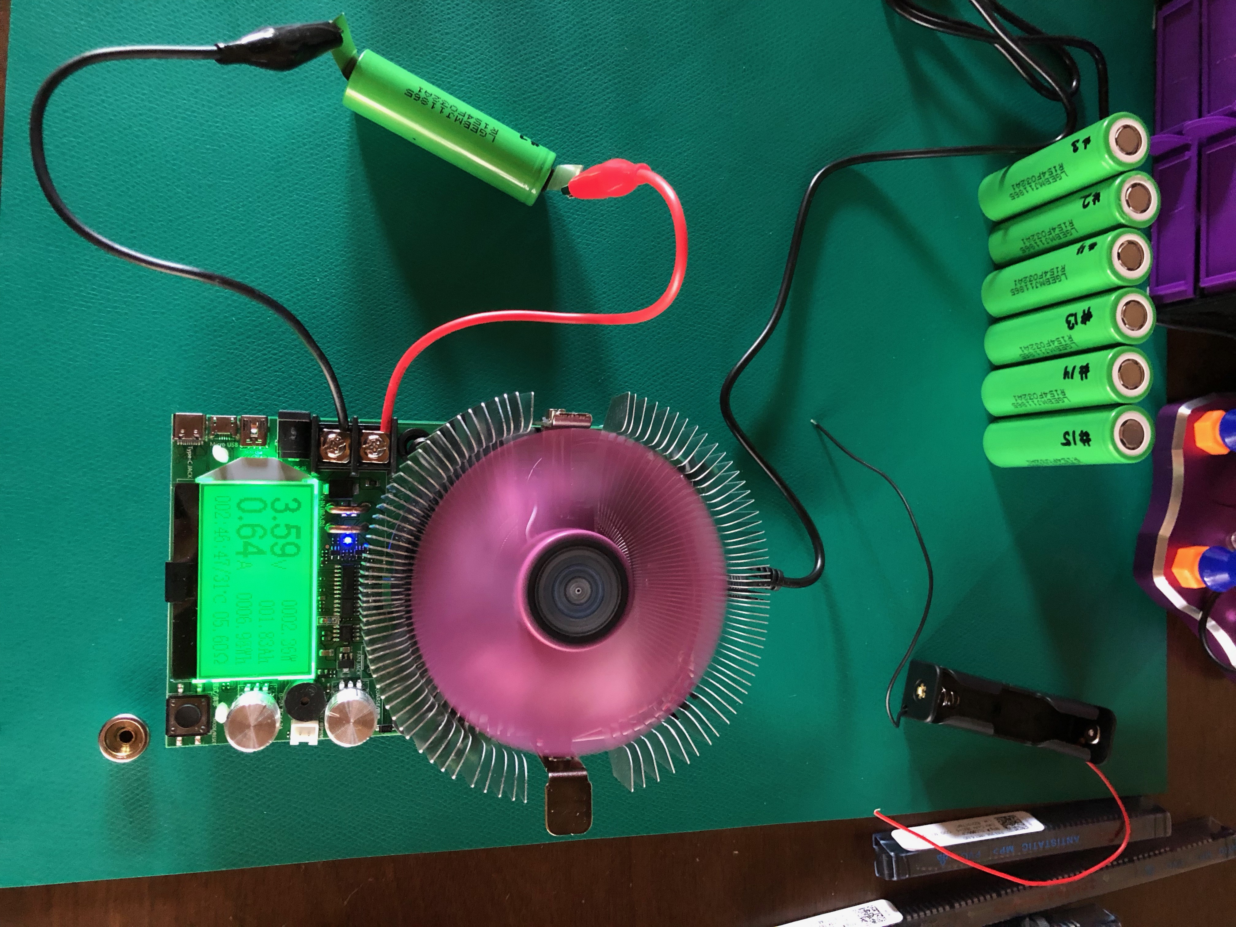
While on searching on Amazon, I stumbled across this device in the picture below. It’s a constant current “load tester” device, a simple, cheap one from China. But it does exactly was I need, for ~$40. What a bargain! And it works as advertised. One minor problem is that it doesn’t know when to stop.
So I set up the device in my office, plug in a cell, and set a timer for 4.5 hours. When the timer goes off, I check on the device and it’s doing great. The cell voltage is getting near the minimum of 2.5V and the measured capacity is at about 3100 mAh. Awesome! Just a few more minutes. So I hang out in my office finding things to keep me busy… a bit too busy. I miss the 2.5V cutoff, the device continues to drain the cell and by the time I realize it was below 2V. Whoops. Well, I’ll catch the next one. Except I didn’t. It got down to 1.5V before I realized. (To be continued… below)
Electronics Apprenticeship
Meanwhile, in other news…. My electrical skills are modest, at best. I’ve dabbled with micro-controllers, hobby boards, and simple circuits. But I had to level up on electronics in order to wire the OneX. To build this electric plane, I’m going to need to level up a few more times in my electrical craftsmanship.
For those who know my background, it’s no surprise that I sought out a mentor for my apprenticeship in electronics. And I was fortunate enough to find one. Chuck Studee is an old friend of my father. They worked together at Teredyne where my dad was a software guy and Chuck was a hardware guy. As a child I remember being fascinated by Chuck’s basement laboratory filled with electrical components, soldering irons, multimeters, oscilliscope, and other gizmos and gadgets. So I reached out to him.
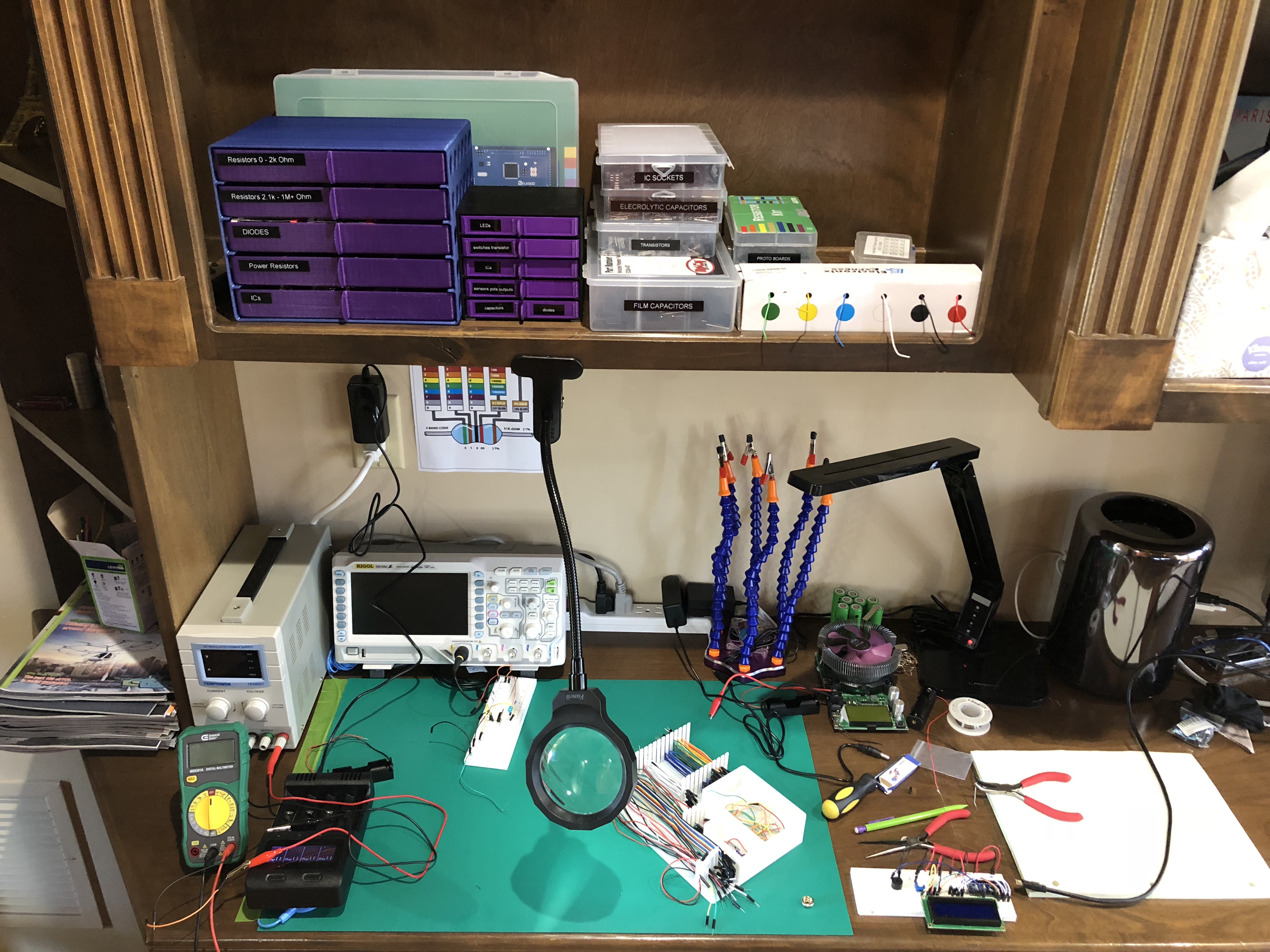
Chuck has been an amazing mentor. He’s full of great stories and depths of knowledge. One of the first things he advised me to do was equip my very own laboratory, stocked with what Chuck calls “jelly bean” parts; resistors, capacitors, transistors, etc. that are commonly used. See the picture below. Being so well equipped has already proved extremely valuable.
I have a backlog of learning experiments to run. Chuck will think of interesting circuits, like Darlington transistor configuration, or an opamp constant current source. We’ll talk about them over the phone and then Chuck will email me a little circuit to wire up and play with. I find these experiments essential for learning. They’re full of surprises. I mean, I’ve recently read electronics books and I’m familiar with the theory, but each time I play with the hands-on examples I learn something new. Sometimes they perplex me so call Chuck and he walks me through it.
With my newly acquired skills, it was time to build a real circuit…
Circuit Diagrams
Back to testing the cell capacity… Draining Li-ion cells below their minimum voltage is not good. Bad things happen. Fire, explosions… So continuing to use the constant current device is not an option. Not unless I’m alerted when the battery is empty (at 2.5V). Hmm… I could build a circuit like that. Use an Arduino to track the cell voltage and sound a piezo buzzer when it gets down to 2.5V. Or better yet, in addition to a buzzer, this “Voltage Alarm” could open the circuit to the load tester and stop the current flow. Perfect!
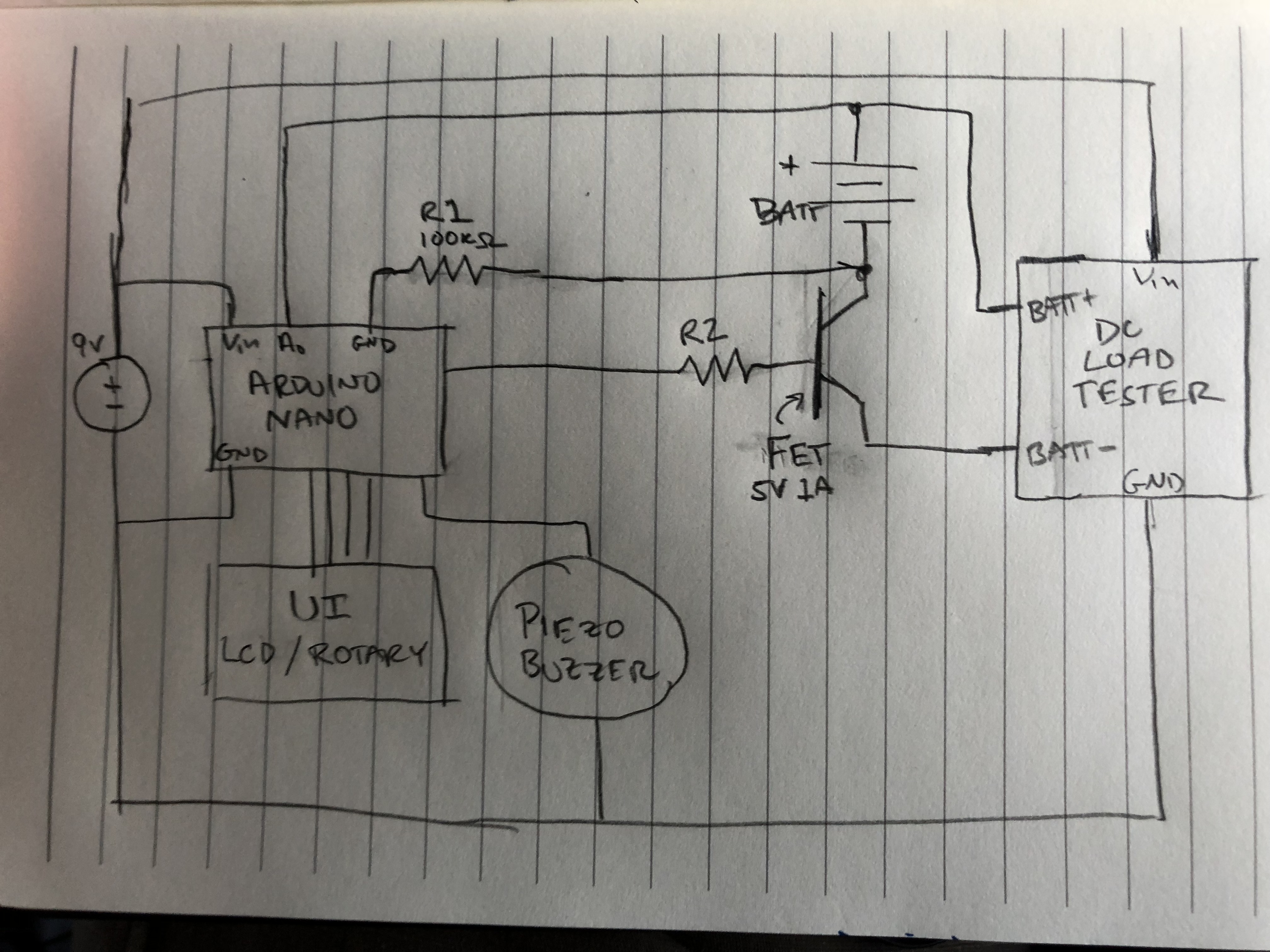
I sketch a circuit that includes an Arduino Nano, a passive piezo buzzer, and a FET (field effect transistor) to open/close the load circuit. And to make the voltage alarm more flexible, and for the fun of it, I include a user interface made of a 16x2 LCD screen and a rotary encoder, the push button kind. I send the picture below to Chuck. He sends back a similar sketch of a circuit, but one that might actually work.
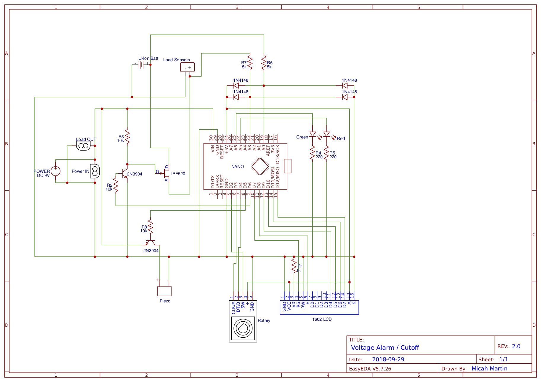
While I’m writing about circuit diagrams, I’ll point out the computer generated schematic (second image below) which is the final representation of the Voltage Alarm.
Arduino Coding
Rather than wire things up, I retreated into my comfort zone; code. C++ code in fact. It ain’t no Clojure or Ruby, but it’s what the Arduino takes; C++. I discovered Google Test, a C++ unit testing framework, and started whipping out code. I may have gotten carried away, building a whole menu structure with configurable settings. The LCD screen can display two rows of text 16 characters wide. And the rotary encoder allows you to navigate the menus by spinning clockwise to scroll down, counter-clockwise to scroll up, and puth-button to select an item. Pretty sweet!
Over about 2 weeks, the circuit came together. Bit by bit, I’d piece together the hardware to make sure the code would run. At one point, everything stopped working. On power up, things would start ok, but then the LCD would display garbage and the Arduino would freeze or reboot over and over. Nothing would fix it except commenting out code that had previously been working fine. Wierd! Turns out I was running out of memory. The Nano has 2k of SRAM, stack and heap combined. My style of programming was apparently quite wasteful with memory. I switched gears and rafactored the code to be very conservative. By the time the entire program was implemented, I had 308 bytes to spare!
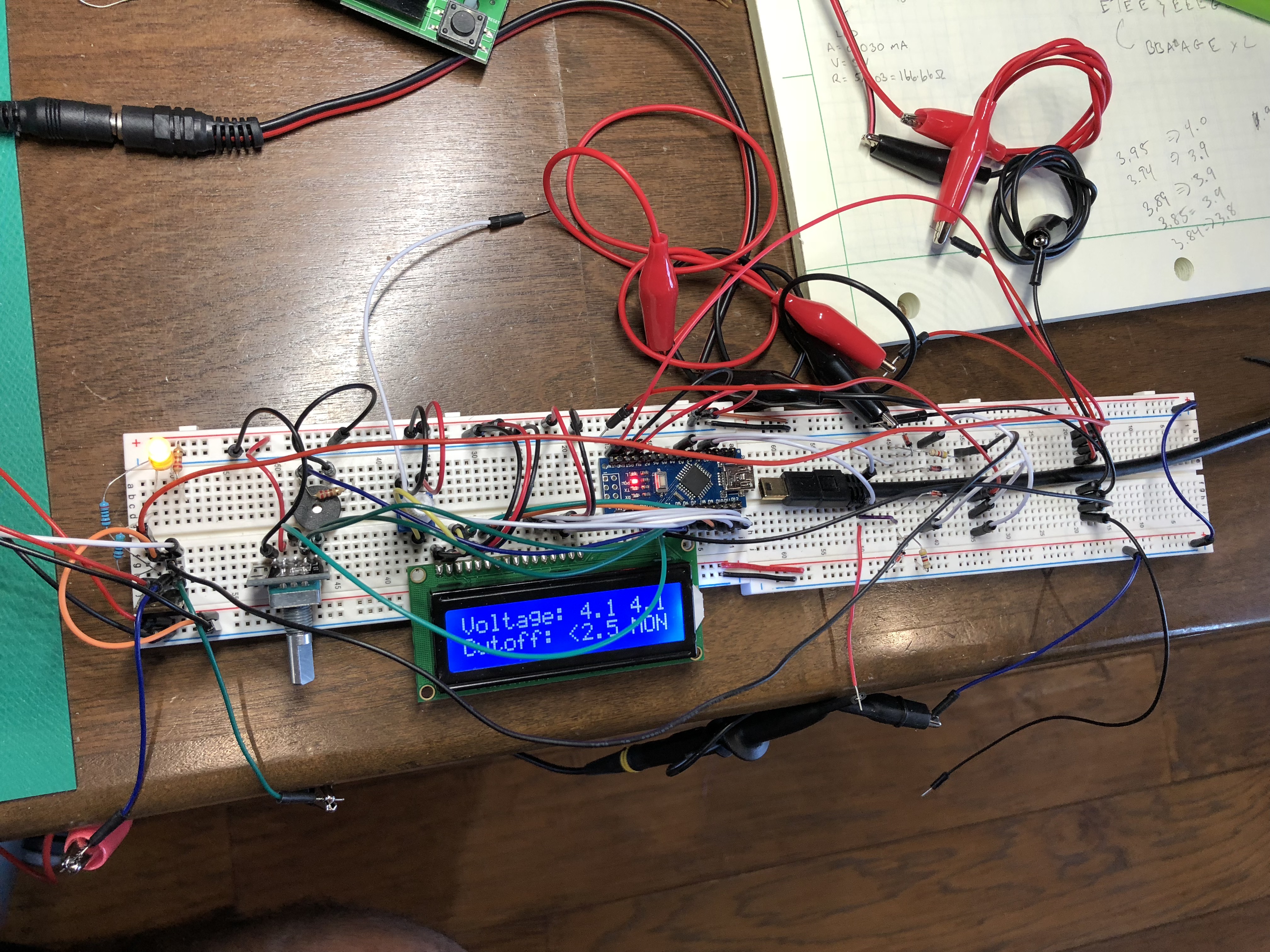
Below is the completed circuit prototype on a couple breadboards. It worked, mostly. The connections on the breadboards are not great and the jumper wires and alligator clips make for flimsy circuits. There were hugh voltage sags between the battery and the load tester with jumpy readings. Nothing a little solder can’t fix, I hoped.
Final Wiring
With the prototype circuit working, I documented the circuit in the schematic above. Choosing the right software was a process of it’s own. Research led me to believe that Eagle, owned by AutoDesk, is the standard. That was good news because I really like AutoDesk’s Fusion 360 CAD tool. I’ve been using Eagle but it’s a bit heavy and seams geared toward final printed circuit board design. I also tried CircuitLab (it was quick to demand money) and few other tools. For now I’ve settled on EasyEDA. It’s easy to use, has all the feature I should need, and it’s free!
Wiring and soldering the final circuit of the Voltage Alarm was a 20 hour project. More time than I imagined. Of course I made newbie mistakes and had to redo several parts. And it didn’t work the first time, or second time. But after debugging the all the wiring problems, it did work. The voltage sag was gone. I could finally test the battery cells without draining them too much.
It only took three weeks to get to that point! -sigh of lamentation-
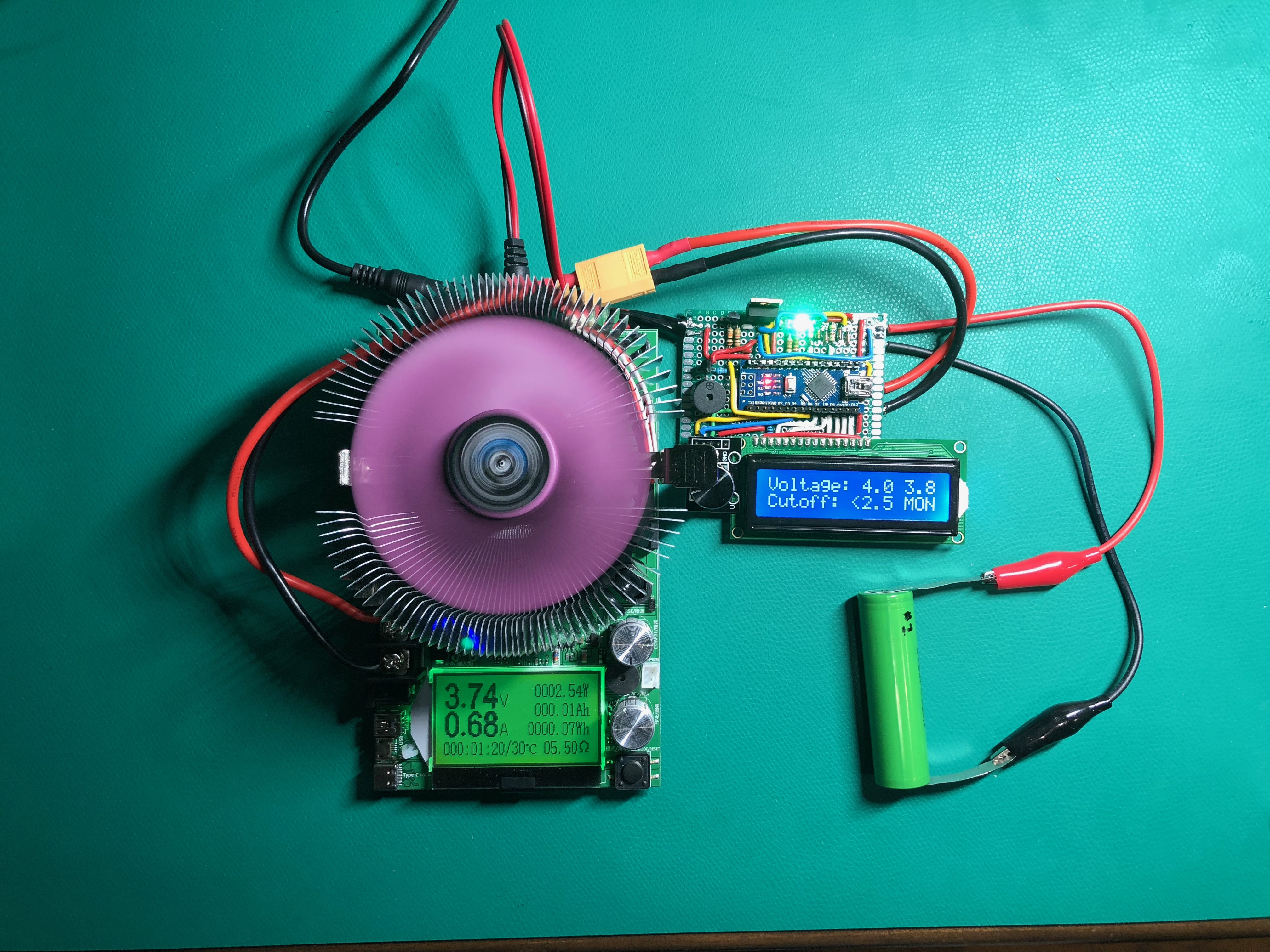
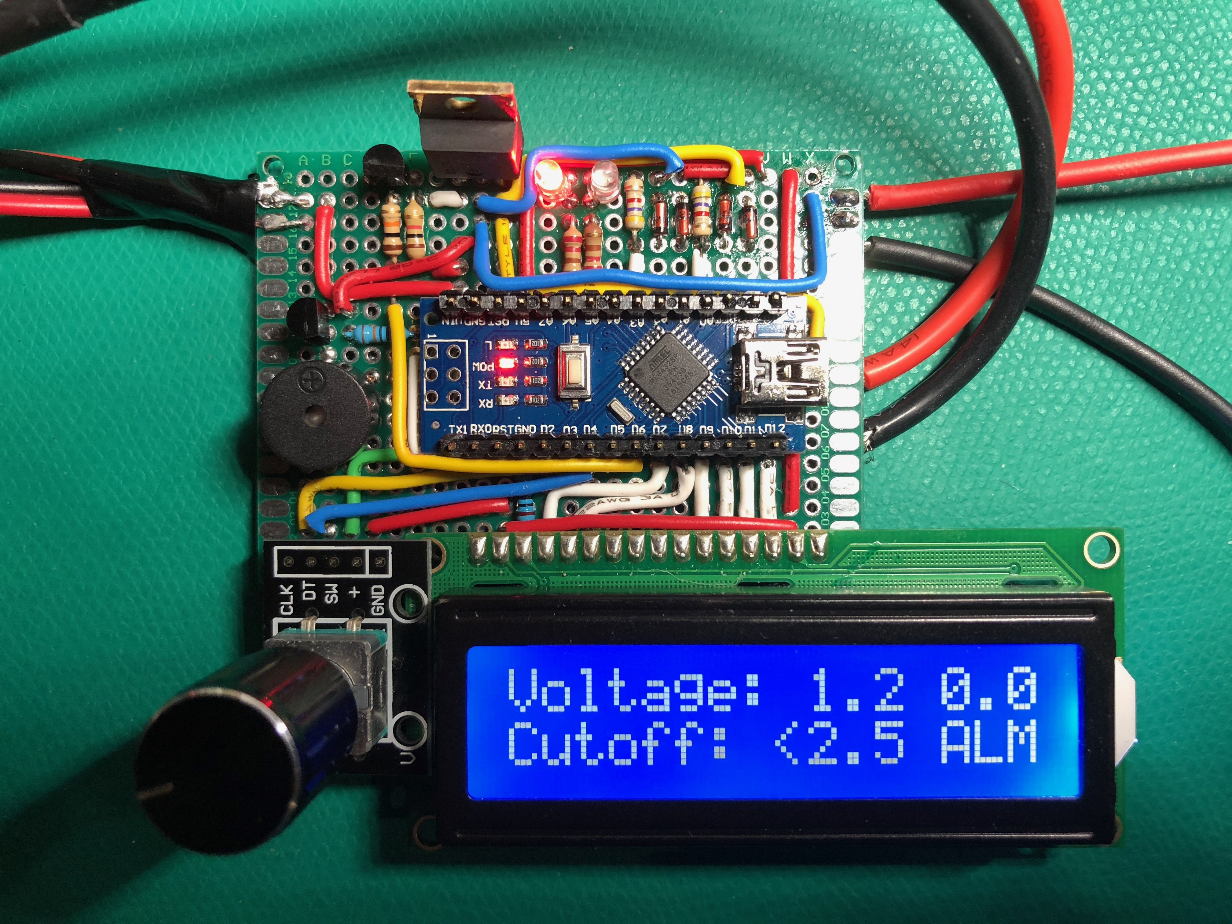
The first picture below is a running test with my Voltage Alarm hooked up to the battery and the constant current load tester. The second is a close up of the Voltage Alarm in the “ALM” (alarm) state. Finally, there’s a video showing how it works at the bottom.